
User's Manual
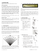
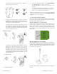
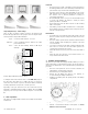


Table Of Contents

UTC. All Rights Reserved. 2 P/N 0000000 – Rev. A – 06 Nov 12
mounting use screws in positions B and/or C. Drill holes in
the base in provided screw locator.
E. An optional swivel mount bracket is available, 6545-BP. The
swivel bracket is used to adjust precisely the motion sensor’s
viewing field. The swivel bracket mounts to the product on the
top rear side for ceiling and wall mounts.
For ceiling mount, (1) position the ceiling bracket base and
secure properly to the ceiling. (2) Insert the swivel into the
base and (3) secure with screw through the product’s swivel
mount. With screw partially inserted make minor adjustments
to sensor’s view angle and secure.
For wall mount, (1) position the wall bracket base and secure
properly to the ceiling material. First insert the top screw
partially into the wall so the screw head can be inserted into
the keyhole opening. Insert second screw into the lower
mounting hole. (2) Insert the swivel into the base and (3)
secure with screw through the product’s swivel mount. With
screw partially inserted make minor adjustments to sensor’s
view angle and secure.
To complete the installation…..
1. Select the desired jumper settings. See the Jumper Adjustment
(1) – switch settings section for more information.
2. Add masking labels if required (see next section for an
example).
3. For ceiling mount applications that require a 90° coverage use
the optional swivel-mount bracket (Part Number: 6545U-BP).
4. Replace cover and tighten the screw in the base.
Note: ensure the battery is inserted properly and/or the battery pull
tab is removed to activate the product. See the Installing / Replacing
Batteries section for more information.
4. Sensor Setup & Jumper Selections
This sensor has two mechanical adjustment and three jumper switches
to aid in your application. After selecting your mounting location within
the room, it’s time to optimize the sensor.
Mechanical Adjustments (1) – Mounting Height
Located on the left side beneath the tamper spring is a PCB legend for
mounting height adjustment. Loosen the PCB mounting screw by
turning counterclockwise so that PCB may slide up and down. Use the
plastic pointer, locate your mounting height and tighten the PCB screw.
By selecting the proper height maximizes the sensors range and
viewing area.
Mechanical Adjustment (2) – Viewing Range
This adjustment allows the sensor’s viewing area to be limited into a
vertical curtain, removing short-range scanning, removing long-range
scanning or any combinations that suits the application. If you know
the desired scanning zone(s) then add masking to the inside surface of
the Fresnel lens as shown below.
Note: left to right: full range, short range removed and ½ vertical range
removed.
A
A
C
C
B
B
3
3