
Service manual


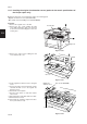


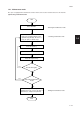

Table Of Contents
- COVER
- CAUTION
- Safety precautions
- CONTENTS
- 1-1 Specifications
- 1-2 Handling Precautions
- 1-3 Installation
- 1-4 Maintenance mode
- 1-5 Trouble Shooting
- 1-5-1 Paper misfeed detection
- 1-5-2 Self-diagnosis
- 1-5-3 Image formation problems
- (1) No image appears (entirely white).
- (2) No image appears (entirely black).
- (3) Image is too light.
- (4) Background is visible.
- (5) A white line appears longitudinally.
- (6) A black line appears longitudinally.
- (7) A black line appears laterally.
- (8) One side of the copy image is darker than the other.
- (9) Black dots appear on the image.
- (10)Image is blurred.
- (11)The leading edge of the image is consistently misaligned with the original.
- (12)The leading edge of the image is sporadically misaligned with the original.
- (13)Paper creases.
- (14)Offset occurs.
- (15)Image is partly missing.
- (16)Fixing is poor.
- (17)Image is out of focus.
- (18)Image center does not align with the original center.
- (19)Image is not square.
- (20)Image contrast is low (carrier scattering).
- 1-5-4 Electrical problems
- (1) The machine does not operate when the main switch is turned on
- (2) The drive motor does not operate when (C200)
- (3) The scanner motor does not operate.
- (4) The toner feed motor does not operate
- (5) Cooling fan motor 1 does not operate
- (6) Cooling fan motor 2 does not operate
- (7) Cooling fan motor 3 does not operate
- (8) The drawer motor does not operate
- (9) The registration clutch does not operate
- (10) The upper paper feed clutch does not operate
- (11) The lower paper clutch does not operate
- (12) Paper feed clutch (ST) 1 does not operate
- (13) Paper feed clutch (ST) 2 does not operate
- (14) The bypass paper feed clutch does not operate
- (15) The cleaning lamp does not turn on
- (16) The exposure lamp does not turn on
- (17) The exposure lamp does not turn off
- (18) The fixing heater does not turn on (C610)
- (19) The fixing heater does not turn off
- (20) Main charging is not performed
- (21) Transfer charging is not performed
- (22) No developing bias is output
- (23) The original size is not detected
- (24) The original size is not detected correctly
- (25) The message requesting papaer to be loaded is shown when paper is present
- (26) The message requesting papaer to be loaded is shown when paper is present in the upper drawer
- (27) The message requesting papaer to be loaded is shown when paper is present in the lower drawer
- (28) The size of paper in the upper drawer is not displayed correctly
- (28) The size of paper in the upper drawer is not displayed correctly
- (29) The size of paper in the lower drawer is not displayed correctly
- (30) The printing width of the paper on the bypass is not detected correctly
- (31) A paper jam in the paper feed, paper conveying or fixing section is indicated when the main switch is turned on
- (32) The message requesting covers to be closed is displayed when the front cover, paper conveying unit and lower drawer left
- (33) Others
- 1-5-5 Mechanical problems
- 1-6 Assembly and disassembly
- 1-6-1 Precautions for assembly and disassembly
- 1-6-2 Paper feed section
- (1) Detaching and refitting the upper and lower paper feed pulleys
- (2) Detaching and refitting the bypass paper feed pulley
- (3) Detaching and refitting the left registration cleaner assembly
- (4) Detaching and refitting the right registration cleaner assembly
- (5) Detaching and refitting the bypass paper width switch
- (6) Adjustment after roller and clutch replacement
- 1-6-3 Optical section
- (1) Detaching and refitting the exposure lamp
- (2) Detaching and refitting the scanner wires
- (3) Detaching and refitting the laser scanner unit
- (4) Adjusting the skew and vertical shifting of the laser scanner unit
- (5) Detaching and refitting the ISU (reference)
- (6) Adjusting the position of the ISU (reference)
- (7) Adjusting the longitudinal squareness (reference)
- (8) Adjusting magnification of the scanner in the main scanning direction
- (9) Adjusting magnification of the scanner in the auxiliary scanning direction
- (10) Adjusting the scanner leading edge registration
- (11)Adjusting the scanner center line
- (12) Adjusting the margins for scanning an original on the contact glass
- 1-6-4 Main charging section
- 1-6-5 Drum section
- 1-6-6 Developing section
- 1-6-7 Transfer section
- 1-6-8 Cleaning section
- 1-6-9 Fixing section
- 1-7 Requirements on PCB Replacement
- 2-1 Electrical Parts Layout
- 2-2 Electrical parts layout
- 2-3 Operation of the PCBs
- 2-4 Appendixes

1-4-2
2AV/X
1-4
(2) Maintenance mode item list (for 20 cpm copier)
Section
Item
Maintenance item contents
Initial
No. setting*
U000 Outputting an own-status report
U001 Exiting the maintenance mode
U003 Setting the service telephone number
U004 Setting the machine number
U005 Copying without paper
U019 Displaying the ROM version
U020 Initializing all data
U021 Initializing memories
U022 Initializing backup data
U030 Checking motor operation
U031 Checking switches for paper conveying
U032 Checking clutch operation
U033 Checking solenoid operation
U034 Adjusting the print start timing
Adjusting leading edge registration
Adjusting the center line
U035 Setting folio size
Length
Width
U051 Adjusting the amount of slack in the paper
At the registration roller
At the paper feed roller
U053 Performing fine adjustment of the motor speed
Drive motor/Polygon motor/Feedshift motor
U060 Adjusting the scanner input properties
U061 Turning the exposure lamp on
U063 Adjusting the shading position
U065 Adjusting the scanner magnification
Main scannning direction/auxiliary scanning direction
U066 Adjusting the leading edge registration for scanning an original on the
contact glass
U067 Adjusting the center line for scanning an original on the contact glass
U070 Adjusting the DF magnification
U071 Adjusting the DF scanning timing
Adjusting the DF leading edge registration
Adjusting the DF trailing edge registration
U072 Adjusting the DF center line
U073 Checking scanner operation
U074 Adjusting the DF input light luminosity
U087 Turning the DF scanning position adjust mode on/off
U088 Setting the input filter (moiré reduction mode)
U091 Checking shading
U092 Adjusting the scanner automatically
U093 Setting the exposure density gradient
U099 Checking the original size detection
U100 Setting the surface potential
U101 Setting high voltages
Developing bias control voltage during image formation
Developing bias control voltage during no image formation
Transfer control voltage
Transfer voltage output timing
U109 Setting the drum type
U110 Checking/clearing the drum count
—
—
***************
0
—
—
—
—
—
—
—
—
—
0
0
330
210
0
0
0
12
—
0
0/0
0
0
0
0
0
0
—
1
On
Off
—
—
0
—
184
193
38
115
–176
H type
—
* Initial setting for executing maintenance item U020
General
Initialization
Drive, paper
feed, paper
conveying and
cooling system
Optical
High voltage