
Service manual

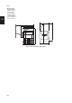

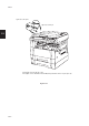


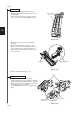
Table Of Contents
- COVER
- CAUTION
- Safety precautions
- CONTENTS
- 1-1 Specifications
- 1-2 Handling Precautions
- 1-3 Installation
- 1-4 Maintenance mode
- 1-5 Trouble Shooting
- 1-5-1 Paper misfeed detection
- 1-5-2 Self-diagnosis
- 1-5-3 Image formation problems
- (1) No image appears (entirely white).
- (2) No image appears (entirely black).
- (3) Image is too light.
- (4) Background is visible.
- (5) A white line appears longitudinally.
- (6) A black line appears longitudinally.
- (7) A black line appears laterally.
- (8) One side of the copy image is darker than the other.
- (9) Black dots appear on the image.
- (10)Image is blurred.
- (11)The leading edge of the image is consistently misaligned with the original.
- (12)The leading edge of the image is sporadically misaligned with the original.
- (13)Paper creases.
- (14)Offset occurs.
- (15)Image is partly missing.
- (16)Fixing is poor.
- (17)Image is out of focus.
- (18)Image center does not align with the original center.
- (19)Image is not square.
- (20)Image contrast is low (carrier scattering).
- 1-5-4 Electrical problems
- (1) The machine does not operate when the main switch is turned on
- (2) The drive motor does not operate when (C200)
- (3) The scanner motor does not operate.
- (4) The toner feed motor does not operate
- (5) Cooling fan motor 1 does not operate
- (6) Cooling fan motor 2 does not operate
- (7) Cooling fan motor 3 does not operate
- (8) The drawer motor does not operate
- (9) The registration clutch does not operate
- (10) The upper paper feed clutch does not operate
- (11) The lower paper clutch does not operate
- (12) Paper feed clutch (ST) 1 does not operate
- (13) Paper feed clutch (ST) 2 does not operate
- (14) The bypass paper feed clutch does not operate
- (15) The cleaning lamp does not turn on
- (16) The exposure lamp does not turn on
- (17) The exposure lamp does not turn off
- (18) The fixing heater does not turn on (C610)
- (19) The fixing heater does not turn off
- (20) Main charging is not performed
- (21) Transfer charging is not performed
- (22) No developing bias is output
- (23) The original size is not detected
- (24) The original size is not detected correctly
- (25) The message requesting papaer to be loaded is shown when paper is present
- (26) The message requesting papaer to be loaded is shown when paper is present in the upper drawer
- (27) The message requesting papaer to be loaded is shown when paper is present in the lower drawer
- (28) The size of paper in the upper drawer is not displayed correctly
- (28) The size of paper in the upper drawer is not displayed correctly
- (29) The size of paper in the lower drawer is not displayed correctly
- (30) The printing width of the paper on the bypass is not detected correctly
- (31) A paper jam in the paper feed, paper conveying or fixing section is indicated when the main switch is turned on
- (32) The message requesting covers to be closed is displayed when the front cover, paper conveying unit and lower drawer left
- (33) Others
- 1-5-5 Mechanical problems
- 1-6 Assembly and disassembly
- 1-6-1 Precautions for assembly and disassembly
- 1-6-2 Paper feed section
- (1) Detaching and refitting the upper and lower paper feed pulleys
- (2) Detaching and refitting the bypass paper feed pulley
- (3) Detaching and refitting the left registration cleaner assembly
- (4) Detaching and refitting the right registration cleaner assembly
- (5) Detaching and refitting the bypass paper width switch
- (6) Adjustment after roller and clutch replacement
- 1-6-3 Optical section
- (1) Detaching and refitting the exposure lamp
- (2) Detaching and refitting the scanner wires
- (3) Detaching and refitting the laser scanner unit
- (4) Adjusting the skew and vertical shifting of the laser scanner unit
- (5) Detaching and refitting the ISU (reference)
- (6) Adjusting the position of the ISU (reference)
- (7) Adjusting the longitudinal squareness (reference)
- (8) Adjusting magnification of the scanner in the main scanning direction
- (9) Adjusting magnification of the scanner in the auxiliary scanning direction
- (10) Adjusting the scanner leading edge registration
- (11)Adjusting the scanner center line
- (12) Adjusting the margins for scanning an original on the contact glass
- 1-6-4 Main charging section
- 1-6-5 Drum section
- 1-6-6 Developing section
- 1-6-7 Transfer section
- 1-6-8 Cleaning section
- 1-6-9 Fixing section
- 1-7 Requirements on PCB Replacement
- 2-1 Electrical Parts Layout
- 2-2 Electrical parts layout
- 2-3 Operation of the PCBs
- 2-4 Appendixes

1-3-1
2AV/X
1-31-3
1-3-1 Unpacking and installation
(1) Installation procedure
Unpack.
Remove the tapes.
Make test copies.
Remove the pins holding light source units 1 and 2.
Load developer.
Adjust the fixing pressure.
Install a waste toner tank.
Connect the power cord.
Load paper.
Install a toner cartridge.
Output an own-status report
(maintenance item U000).
Exit maintenance mode.
Start
Remove the image formation unit.
Release the cleaning blade.
Carry out initial developer setting
(maintenance item U130).
Install the optional devices.
Completion of the machine installation.