
Service manual


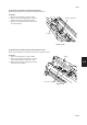
Table Of Contents
- COVER
- CAUTION
- Safety precautions
- CONTENTS
- 1-1 Specifications
- 1-2 Handling Precautions
- 1-3 Installation
- 1-4 Maintenance mode
- 1-5 Trouble Shooting
- 1-5-1 Paper misfeed detection
- 1-5-2 Self-diagnosis
- 1-5-3 Image formation problems
- (1) No image appears (entirely white).
- (2) No image appears (entirely black).
- (3) Image is too light.
- (4) Background is visible.
- (5) A white line appears longitudinally.
- (6) A black line appears longitudinally.
- (7) A black line appears laterally.
- (8) One side of the copy image is darker than the other.
- (9) Black dots appear on the image.
- (10)Image is blurred.
- (11)The leading edge of the image is consistently misaligned with the original.
- (12)The leading edge of the image is sporadically misaligned with the original.
- (13)Paper creases.
- (14)Offset occurs.
- (15)Image is partly missing.
- (16)Fixing is poor.
- (17)Image is out of focus.
- (18)Image center does not align with the original center.
- (19)Image is not square.
- (20)Image contrast is low (carrier scattering).
- 1-5-4 Electrical problems
- (1) The machine does not operate when the main switch is turned on
- (2) The drive motor does not operate when (C200)
- (3) The scanner motor does not operate.
- (4) The toner feed motor does not operate
- (5) Cooling fan motor 1 does not operate
- (6) Cooling fan motor 2 does not operate
- (7) Cooling fan motor 3 does not operate
- (8) The drawer motor does not operate
- (9) The registration clutch does not operate
- (10) The upper paper feed clutch does not operate
- (11) The lower paper clutch does not operate
- (12) Paper feed clutch (ST) 1 does not operate
- (13) Paper feed clutch (ST) 2 does not operate
- (14) The bypass paper feed clutch does not operate
- (15) The cleaning lamp does not turn on
- (16) The exposure lamp does not turn on
- (17) The exposure lamp does not turn off
- (18) The fixing heater does not turn on (C610)
- (19) The fixing heater does not turn off
- (20) Main charging is not performed
- (21) Transfer charging is not performed
- (22) No developing bias is output
- (23) The original size is not detected
- (24) The original size is not detected correctly
- (25) The message requesting papaer to be loaded is shown when paper is present
- (26) The message requesting papaer to be loaded is shown when paper is present in the upper drawer
- (27) The message requesting papaer to be loaded is shown when paper is present in the lower drawer
- (28) The size of paper in the upper drawer is not displayed correctly
- (28) The size of paper in the upper drawer is not displayed correctly
- (29) The size of paper in the lower drawer is not displayed correctly
- (30) The printing width of the paper on the bypass is not detected correctly
- (31) A paper jam in the paper feed, paper conveying or fixing section is indicated when the main switch is turned on
- (32) The message requesting covers to be closed is displayed when the front cover, paper conveying unit and lower drawer left
- (33) Others
- 1-5-5 Mechanical problems
- 1-6 Assembly and disassembly
- 1-6-1 Precautions for assembly and disassembly
- 1-6-2 Paper feed section
- (1) Detaching and refitting the upper and lower paper feed pulleys
- (2) Detaching and refitting the bypass paper feed pulley
- (3) Detaching and refitting the left registration cleaner assembly
- (4) Detaching and refitting the right registration cleaner assembly
- (5) Detaching and refitting the bypass paper width switch
- (6) Adjustment after roller and clutch replacement
- 1-6-3 Optical section
- (1) Detaching and refitting the exposure lamp
- (2) Detaching and refitting the scanner wires
- (3) Detaching and refitting the laser scanner unit
- (4) Adjusting the skew and vertical shifting of the laser scanner unit
- (5) Detaching and refitting the ISU (reference)
- (6) Adjusting the position of the ISU (reference)
- (7) Adjusting the longitudinal squareness (reference)
- (8) Adjusting magnification of the scanner in the main scanning direction
- (9) Adjusting magnification of the scanner in the auxiliary scanning direction
- (10) Adjusting the scanner leading edge registration
- (11)Adjusting the scanner center line
- (12) Adjusting the margins for scanning an original on the contact glass
- 1-6-4 Main charging section
- 1-6-5 Drum section
- 1-6-6 Developing section
- 1-6-7 Transfer section
- 1-6-8 Cleaning section
- 1-6-9 Fixing section
- 1-7 Requirements on PCB Replacement
- 2-1 Electrical Parts Layout
- 2-2 Electrical parts layout
- 2-3 Operation of the PCBs
- 2-4 Appendixes

2AV/X
1-6-43
1-6
1-6-5 Drum section
(1) Detaching and refitting the drum
Follow the procedure below to replace the drum.
Cautions:
• Avoid direct sunlight or strong light when detaching and fitting the drum.
• Hold the drum at the ends and never touch the drum surface.
• After removing the drum, keep it in the drum case or storage bag to protect the surface from light.
Procedure
1. Remove the image formation unit (see page
1-6-40).
2. Remove the two screws holding the transfer
right guide and then the guide.
3. Remove the screw holding each of the three
drum separation claw assemblies and then
the assemblies.
Figure 1-6-57
4. Pull the drum shaft out and replace the drum.
• Check the letter indicating the drum type (G,
H or J) printed on the new drum flange.
• When fitting the drum, orient it correctly so
that the gear is positioned at the machine
rear.
• When fitting the drum shaft, insert it fully.
Figure 1-6-58
5. Remove the front image formation unit cover.
Rub the contacting surfaces of the drum shaft
and drum drive grounding plate with a cloth
and then apply the GE-334C conductive
grease (P/N A0199040) to the contacting
surfaces of the grounding plate. Refit the
removed parts.
6. After replacing the drum, run maintenance
items below.
• U109 “Setting the drum type “ (set to the
drum type printed on the new drum flange)
• U110 “Checking/clearing the drum
count”(clear the drum count)
• U111 “Checking/clearing the drum drive
time” (clear the value)
Figure 1-6-59
Drum separation claw assemblies
Transfer right guide
Drum
Drum shaft
Drum shaft
Drum drive grounding plate