
Service manual


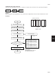


Table Of Contents
- COVER
- CAUTION
- Safety precautions
- CONTENTS
- 1-1 Specifications
- 1-2 Handling Precautions
- 1-3 Installation
- 1-4 Maintenance mode
- 1-5 Trouble Shooting
- 1-5-1 Paper misfeed detection
- 1-5-2 Self-diagnosis
- 1-5-3 Image formation problems
- (1) No image appears (entirely white).
- (2) No image appears (entirely black).
- (3) Image is too light.
- (4) Background is visible.
- (5) A white line appears longitudinally.
- (6) A black line appears longitudinally.
- (7) A black line appears laterally.
- (8) One side of the copy image is darker than the other.
- (9) Black dots appear on the image.
- (10)Image is blurred.
- (11)The leading edge of the image is consistently misaligned with the original.
- (12)The leading edge of the image is sporadically misaligned with the original.
- (13)Paper creases.
- (14)Offset occurs.
- (15)Image is partly missing.
- (16)Fixing is poor.
- (17)Image is out of focus.
- (18)Image center does not align with the original center.
- (19)Image is not square.
- (20)Image contrast is low (carrier scattering).
- 1-5-4 Electrical problems
- (1) The machine does not operate when the main switch is turned on
- (2) The drive motor does not operate when (C200)
- (3) The scanner motor does not operate.
- (4) The toner feed motor does not operate
- (5) Cooling fan motor 1 does not operate
- (6) Cooling fan motor 2 does not operate
- (7) Cooling fan motor 3 does not operate
- (8) The drawer motor does not operate
- (9) The registration clutch does not operate
- (10) The upper paper feed clutch does not operate
- (11) The lower paper clutch does not operate
- (12) Paper feed clutch (ST) 1 does not operate
- (13) Paper feed clutch (ST) 2 does not operate
- (14) The bypass paper feed clutch does not operate
- (15) The cleaning lamp does not turn on
- (16) The exposure lamp does not turn on
- (17) The exposure lamp does not turn off
- (18) The fixing heater does not turn on (C610)
- (19) The fixing heater does not turn off
- (20) Main charging is not performed
- (21) Transfer charging is not performed
- (22) No developing bias is output
- (23) The original size is not detected
- (24) The original size is not detected correctly
- (25) The message requesting papaer to be loaded is shown when paper is present
- (26) The message requesting papaer to be loaded is shown when paper is present in the upper drawer
- (27) The message requesting papaer to be loaded is shown when paper is present in the lower drawer
- (28) The size of paper in the upper drawer is not displayed correctly
- (28) The size of paper in the upper drawer is not displayed correctly
- (29) The size of paper in the lower drawer is not displayed correctly
- (30) The printing width of the paper on the bypass is not detected correctly
- (31) A paper jam in the paper feed, paper conveying or fixing section is indicated when the main switch is turned on
- (32) The message requesting covers to be closed is displayed when the front cover, paper conveying unit and lower drawer left
- (33) Others
- 1-5-5 Mechanical problems
- 1-6 Assembly and disassembly
- 1-6-1 Precautions for assembly and disassembly
- 1-6-2 Paper feed section
- (1) Detaching and refitting the upper and lower paper feed pulleys
- (2) Detaching and refitting the bypass paper feed pulley
- (3) Detaching and refitting the left registration cleaner assembly
- (4) Detaching and refitting the right registration cleaner assembly
- (5) Detaching and refitting the bypass paper width switch
- (6) Adjustment after roller and clutch replacement
- 1-6-3 Optical section
- (1) Detaching and refitting the exposure lamp
- (2) Detaching and refitting the scanner wires
- (3) Detaching and refitting the laser scanner unit
- (4) Adjusting the skew and vertical shifting of the laser scanner unit
- (5) Detaching and refitting the ISU (reference)
- (6) Adjusting the position of the ISU (reference)
- (7) Adjusting the longitudinal squareness (reference)
- (8) Adjusting magnification of the scanner in the main scanning direction
- (9) Adjusting magnification of the scanner in the auxiliary scanning direction
- (10) Adjusting the scanner leading edge registration
- (11)Adjusting the scanner center line
- (12) Adjusting the margins for scanning an original on the contact glass
- 1-6-4 Main charging section
- 1-6-5 Drum section
- 1-6-6 Developing section
- 1-6-7 Transfer section
- 1-6-8 Cleaning section
- 1-6-9 Fixing section
- 1-7 Requirements on PCB Replacement
- 2-1 Electrical Parts Layout
- 2-2 Electrical parts layout
- 2-3 Operation of the PCBs
- 2-4 Appendixes
2AV/X
1-6-39
1-6
• 15 cpm
Change the setting.
Increasing the value using the zoom
(+) key makes the margin wider.
Decreasing the value using the
zoom (–) key makes the margin
narrower.
Yes
No
Start
Enter maintenance mode.
Enter “403” using the numeric keys.
Press the start key.
Press the start key
to make a test copy.
Press the start key.
The new setting
is stored.
Setting range (default)
Scanner left margin: 0 – +10 (2)
Scanner leading edge margin: 0 – +10 (3)
Scanner right margin: 0 – +10 (2)
Scanner trailing edge margin: 0 – +10 (2)
Changing the value by one moves
the margin by 0.5 mm for all.
Select the item to be adjusted using
the copy exposure adjustment keys.
Are the margins correct?
Press the interrupt key.
Yes
No
Proceed to another mode?
End
Press the stop/clear key to
exit maintenance mode.
● Copy exposure adjustment keys
Setting 1 : scanner left margin
2 : scanner leading edge margin
3 : scanner right margin
4 : scanner trailing edge margin
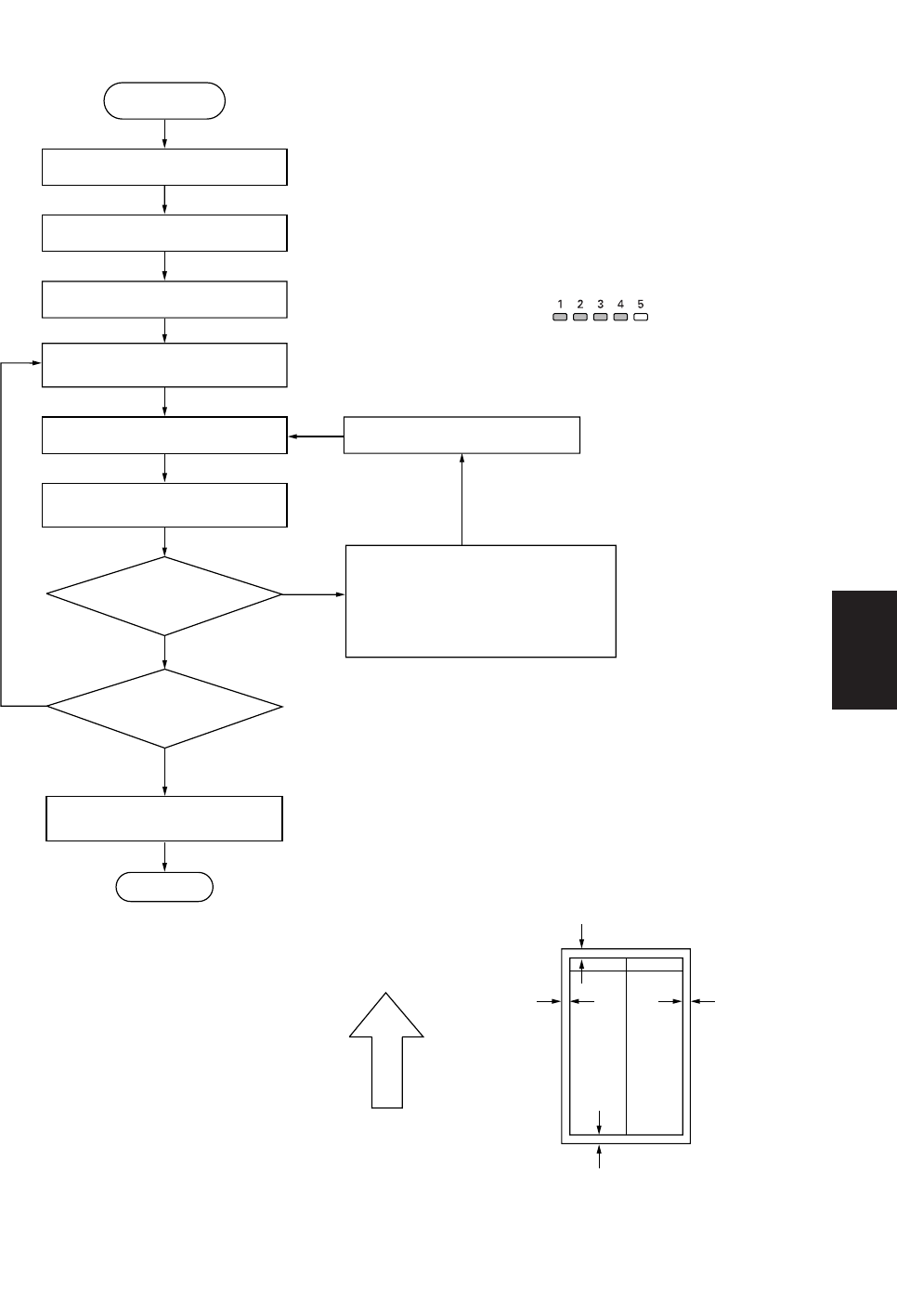
Scanner leading edge margin (3 ± 2.5 mm)
Scanner
left margin
(2
+2.0
mm)
Scanner
right margin
(2
+2.0
mm)
Ejection direction
(reference)
Scanner trailing edge margin
(2
+2.0
mm)
–1.5
–1.5
–1.5