
Service manual


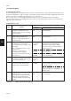

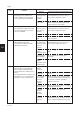


Table Of Contents
- COVER
- CAUTION
- Safety precautions
- CONTENTS
- 1-1 Specifications
- 1-2 Handling Precautions
- 1-3 Installation
- 1-4 Maintenance mode
- 1-5 Trouble Shooting
- 1-5-1 Paper misfeed detection
- 1-5-2 Self-diagnosis
- 1-5-3 Image formation problems
- (1) No image appears (entirely white).
- (2) No image appears (entirely black).
- (3) Image is too light.
- (4) Background is visible.
- (5) A white line appears longitudinally.
- (6) A black line appears longitudinally.
- (7) A black line appears laterally.
- (8) One side of the copy image is darker than the other.
- (9) Black dots appear on the image.
- (10)Image is blurred.
- (11)The leading edge of the image is consistently misaligned with the original.
- (12)The leading edge of the image is sporadically misaligned with the original.
- (13)Paper creases.
- (14)Offset occurs.
- (15)Image is partly missing.
- (16)Fixing is poor.
- (17)Image is out of focus.
- (18)Image center does not align with the original center.
- (19)Image is not square.
- (20)Image contrast is low (carrier scattering).
- 1-5-4 Electrical problems
- (1) The machine does not operate when the main switch is turned on
- (2) The drive motor does not operate when (C200)
- (3) The scanner motor does not operate.
- (4) The toner feed motor does not operate
- (5) Cooling fan motor 1 does not operate
- (6) Cooling fan motor 2 does not operate
- (7) Cooling fan motor 3 does not operate
- (8) The drawer motor does not operate
- (9) The registration clutch does not operate
- (10) The upper paper feed clutch does not operate
- (11) The lower paper clutch does not operate
- (12) Paper feed clutch (ST) 1 does not operate
- (13) Paper feed clutch (ST) 2 does not operate
- (14) The bypass paper feed clutch does not operate
- (15) The cleaning lamp does not turn on
- (16) The exposure lamp does not turn on
- (17) The exposure lamp does not turn off
- (18) The fixing heater does not turn on (C610)
- (19) The fixing heater does not turn off
- (20) Main charging is not performed
- (21) Transfer charging is not performed
- (22) No developing bias is output
- (23) The original size is not detected
- (24) The original size is not detected correctly
- (25) The message requesting papaer to be loaded is shown when paper is present
- (26) The message requesting papaer to be loaded is shown when paper is present in the upper drawer
- (27) The message requesting papaer to be loaded is shown when paper is present in the lower drawer
- (28) The size of paper in the upper drawer is not displayed correctly
- (28) The size of paper in the upper drawer is not displayed correctly
- (29) The size of paper in the lower drawer is not displayed correctly
- (30) The printing width of the paper on the bypass is not detected correctly
- (31) A paper jam in the paper feed, paper conveying or fixing section is indicated when the main switch is turned on
- (32) The message requesting covers to be closed is displayed when the front cover, paper conveying unit and lower drawer left
- (33) Others
- 1-5-5 Mechanical problems
- 1-6 Assembly and disassembly
- 1-6-1 Precautions for assembly and disassembly
- 1-6-2 Paper feed section
- (1) Detaching and refitting the upper and lower paper feed pulleys
- (2) Detaching and refitting the bypass paper feed pulley
- (3) Detaching and refitting the left registration cleaner assembly
- (4) Detaching and refitting the right registration cleaner assembly
- (5) Detaching and refitting the bypass paper width switch
- (6) Adjustment after roller and clutch replacement
- 1-6-3 Optical section
- (1) Detaching and refitting the exposure lamp
- (2) Detaching and refitting the scanner wires
- (3) Detaching and refitting the laser scanner unit
- (4) Adjusting the skew and vertical shifting of the laser scanner unit
- (5) Detaching and refitting the ISU (reference)
- (6) Adjusting the position of the ISU (reference)
- (7) Adjusting the longitudinal squareness (reference)
- (8) Adjusting magnification of the scanner in the main scanning direction
- (9) Adjusting magnification of the scanner in the auxiliary scanning direction
- (10) Adjusting the scanner leading edge registration
- (11)Adjusting the scanner center line
- (12) Adjusting the margins for scanning an original on the contact glass
- 1-6-4 Main charging section
- 1-6-5 Drum section
- 1-6-6 Developing section
- 1-6-7 Transfer section
- 1-6-8 Cleaning section
- 1-6-9 Fixing section
- 1-7 Requirements on PCB Replacement
- 2-1 Electrical Parts Layout
- 2-2 Electrical parts layout
- 2-3 Operation of the PCBs
- 2-4 Appendixes

2AV/X
1-5-11
Problem Causes/check procedures Corrective measures
1-5
*1: Standard for 20 cpm copier/optional for 15 cpm copier. *2: Optional for both 20 cpm and 15 cpm copiers.
(10)
A paper jam in the
paper feed section
is indicated during
copying (multiple
sheets in vertical
paper conveying
section).
(11)
A paper jam in the
paper feed section
is indicated during
copying (multiple
sheets in bypass).
(12)
A paper jam in the
paper conveying
section is indicated
during copying (jam
in registration/
transfer section).
(13)
A paper jam in the
fixing section is
indicated during
copying (jam in
fixing section).
(14)
A paper jam in the
eject section is
indicated during
copying (jam in eject
section).
Broken drawer feed
switch*
1
actuator.
Defective drawer feed
switch*
1
.
Broken registration switch
actuator.
Defective registration
switch.
Check if the right and left
registration rollers contact
each other.
Broken drawer feed
switch*
1
actuator.
Defective drawer feed
switch*
1
.
Broken registration switch
actuator.
Defective registration
switch.
Check if the registration
clutch malfunctions.
Electrical problem with the
registration clutch.
Broken eject switch
actuator.
Defective eject switch.
Broken registration switch
actuator.
Defective registration
switch.
Broken eject switch
actuator.
Defective eject switch.
Check visually and replace the drawer feed switch*
1
if its
actuator is broken.
With 5 V DC present at CN8-21 on the main PCB, check if CN8-
23 on the main PCB remains low when the drawer feed switch*
1
is turned on and off. If it does, replace the drawer feed switch*
1
.
Check visually and replace the registration switch if its actuator
is broken.
With 5 V DC present at CN3-6 on the main PCB, check if CN3-7
on the main PCB remains low when the registration switch is
turned on and off. If it does, replace the registration switch.
Check visually and remedy if necessary.
Check visually and replace the drawer feed switch*
1
if its
actuator is broken.
With 5 V DC present at CN8-21 on the main PCB, check if CN8-
23 on the main PCB remains low when the drawer feed switch*
1
is turned on and off. If it does, replace the drawer feed switch*
1
.
Check visually and replace the registration switch if its actuator
is broken.
With 5 V DC present at CN3-6 on the main PCB, check if CN3-7
on the main PCB remains low when the registration switch is
turned on and off. If it does, replace the registration switch.
Check and remedy if necessary.
Check (see page 1-5-26).
Check visually and replace the eject switch if its actuator is
broken.
With 5 V DC present at CN12-7 on the main PCB, check if
CN12-6 on the main PCB remains low when the eject switch is
turned on and off. If it does, replace the eject switch.
Check visually and replace the registration switch if its actuator
is broken.
With 5 V DC present at CN3-6 on the main PCB, check if CN3-7
on the main PCB remains low when the registration switch is
turned on and off. If it does, replace the registration switch.
Check visually and replace the eject switch if its actuator is
broken.
With 5 V DC present at CN12-7 on the main PCB, check if
CN12-6 on the main PCB remains low when the eject switch is
turned on and off. If it does, replace the eject switch.