TM ENTERPRISE NETWORK HUB SYSTEM NETServer/8 NETServer/16 Version 3.
Copyright 1996 by U.S. Robotics Access Corp. 8100 North McCormick Blvd. Skokie, Illinois 60076 All Rights Reserved U.S. Robotics and the U.S. Robotics logo are registered trademarks of U.S. Robotics Access Corp., Total Control is a trademark of U.S. Robotics Access Corp. Any trademarks, tradenames, service marks or service names owned or registered by any other company and used in this manual are the property of their respective companies.
Table of Contents Warranty and Service Chapter 1 Overview What’s New in 3.
Chapter 5 Network Dial-in Access Dial-In User Setup NETServer Dial-In Setup (Overview) NETServer Dial-In (Detailed Setup) Configuring a Port Adding a Network User to the User Table IP Remote Access Case Study IPX Remote Access Case Study Chapter 6 5-1 5-2 5-4 5-4 5-6 5-11 5-15 LAN-to-LAN Routing Setup for NETServer Routing (Overview) An Introduction to NETServer Routing PAP and CHAP Authentication LAN-to-LAN Routing (Detailed Setup) Configuring a Port Adding a Remote Device to the Location Table Addin
Chapter 9 Administrative Tools Configuring the !root Account Manually Connecting to a Remote Site Troubleshooting Commands The SHOW commmand Chapter 10 9-1 9-3 9-4 9-11 Command Reference Global Configuration Hosts Table Configuration Location Table LAN Port (Net0) Configuration Netmasks Table Configuration Ports Table (S-port configuration) Routes Table Configuration SNMP Table User Table 10-1 10-13 10-14 10-24 10-30 10-31 10-49 10-54 10-57 Reference Section Appendix A Technical Specifications App
Warranty and Service Limited Warranty U.S. Robotics Access Corp. warrants to the original consumer or other end user purchaser that all U.S. Robotics Total Control products and parts are free from defects in materials or workmanship for a period of two years from the date of purchase. During the warranty period, and upon proof of purchase, the product will be repaired or replaced (with the same or similar model) at our option, without charge for either parts or labor.
Service and Support To obtain service, contact the U.S. Robotics Systems Product Support Department as described below. Whichever method you use to contact us, please have the product serial number(s) available. Technical Support For technical assistance, contact USR in one of the following ways: Mail 8100 North McCormick Blvd. Skokie, Illinois 60076-2999 E-Mail support@usr.
We welcome your suggestions for better documentation Every effort has been made to provide useful, accurate information. If you have any comments or suggestions, please let us know. viii By voicemail: (708) 933-5200 Via the Internet: sysdocs@usr.
Chapter 1 Overview This chapter provides an overview of the Total Control NETServer/8 and NETServer/16. It also contains information on what’s new in version 3.1 of the NETServer firmware. What’s New with Release 3.1? Release 3.1 supports the following new features: • Classless InterDomain Routing and Host-based routing via the Netmask Table. • IP address spoofing. • Support for RADIUS accounting servers, ANI/DNIS, and ICMP message logging. • Support for a secondary and a tertiary name server.
Netmask Table CIDR (Classless Interdomain Routing) or host-based routing requires special netmasks. Special netmasks may also be useful for debugging. The Netmask Table allows you to configure netmasks for CIDR or host-based routing as needed. RIP messaging/dynamic route information must be active for host-based routing. IP Address Spoofing The NETServer may now be configured to spoof a single IP address.
RADIUS Accounting and ANI/DNIS Release 3.1 of the NETServer supports the current RADIUS Accounting Internet Draft. The NETServer can generate appropriate Code 4 Accounting-Request and Code 5 Accounting-Response messages for properly configured RADIUS servers. The NETServer’s RADIUS implementation also supports ANI and DNIS services. ICMP Message Logging If your system uses syslog network accounting, you can configure the NETServer to send ICMP error messages to the syslog server.
New Modem Port Features Release 3.1 of the NETServer Command Line and NETServer Manager software now support the following modem port features: • Download new firmware to the modems using NETServer Manager (windows software) version 3.2 or later. • You can now send AT commands directly to the modems from the NETServer’s command line.
NETServer Overview The NETServer allows you to implement four basic applications: IP Terminal Service, IP modem sharing, IP/IPX Network Dial In, and IP/IPX LAN-to-LAN routing. Everything else it does is based on one of these four. IP Terminal Service Remote terminals can log into an IP host on the NETServer’s local network as of they were physically connected to it. To do this, the NETServer receives TTY terminal output (keystrokes) over a dial up line.
IP Modem Sharing Hosts on a local IP network can use a chassis modem to dial out. Moreover, the NETServer can create pools of modems that can be used by local hosts on a first come, first serve basis. To do this, the NETServer allows the host to establish a virtual terminal session with the modem. The host can then interact with the modem’s command line and from there, dial out.
Dial-Up Routing The same routing engine that allows network dial in access allows the NETServer to establish dial up routing sessions with remote networks. Such connections can be maintained continuously or established on an on-demand basis and torn down when not needed. How do I get there from here? Configuring any of these applications on a NETServer is a threestep process: 1. Perform basic configuration for the NETServer.
Security The NETServer supports IP and IPX packet filtering in both the inbound and the outbound directions of ports, users, and dial out locations. Packet filter configuration is discussed in Chapter 8. The NETServer also supports the use of a centralized RADIUS security server, allowing you to create a single account for each user rather than multiple user accounts on multiple NETServers. RADIUS security is discussed in Appendix F.
Chapter 2 Basic Installation This chapter contains information on the following: • System Administrator Requirements • Logging into the supervisor account for the first time • Getting the LAN port up and running • Recommended Additional Configuration System Administrator Requirements In compiling this manual, we have had to make certain assumptions about the knowledge of users who will install the product.
TCP/IP Reference Material It is the responsibility of the Network Manager to devise an addressing strategy appropriate for the size and growth potential of the network. We recommend the following reference material for TCP/IP: Comer, D.E., Internetworking with TCP/IP Volume I: Principles, Protocols and Architecture, Prentice-Hall, Englewood Cliffs, New Jersey, 1995. IP machines and networks that will be attached to the Internet must obtain registered addresses from the Internet’s Network Information Center.
Accessing the Command Line To configure the NETServer from the command line, you must log in as the supervisor. 1. In order to login, you need a login prompt. There are three ways to get one: • Attach the provided serial cable to the CONSOLE port and attach the other end of the cable to a terminal (or a PC running terminal emulation software such as Windows Terminal). See the Quick Start Guide for more information.
Getting Started Name your NETServer. Among other things, this name will be used for the NETServer’s DNS system name and its SNMP system name. It is also the name that the NETServer will advertise in SAP broadcasts. No other device on your network should be using this name. Use the following command: set sysname Enter The next thing you need to do is get your NETServer talking to the network attached to its LAN port.
Getting the LAN port up and running First step for IPX or IP/IPX networks If your network uses the IPX protocol, you must enter the IPX network number of the segment the NETServer connected to the NETServer’s LAN port. You can find this network number using Novell’s CONFIG utility. For File Servers Running Novell Version 3.xx 1. Go to the console of a file server that is on the same network segment that the NETServer is on. 2.
This is an example of the information returned for one version 3.xx card that has two different frame types. The card has one port address, but two LAN protocol network addresses, one for each frame type. The network number for 802.3 is 00000255, and for 802.2 it is 00000684. 4. Write down the LAN protocol IPX network number for the frame type you want to use. For File Servers Running Novell Version 2.xx 1. Go to the console of a file server that is on the same network segment that the NETServer is on.
IP Configuration 1. IP Network Address: You must assign an IP address to the NETServer’s LAN interface (Ethernet or Token Ring port). Type the following: Enter set net0 address If your network does not use IP, you may choose whatever address you like. See Appendix B for some basics on TCP/ IP addressing. However, if you want to connect the NETServer to the Internet (even indirectly), the address must be unique in the world.
3. You must also set the Broadcast Address. Type the following: set net0 broadcast Enter High The bits of the host portion of a broadcast address are all ones. This is the rule for the vast majority of IP networks. Low The bits of the host portion of a broadcast address are all zeroes. This is rare, but is still used by some systems including Sun OS 4.x (Solaris 1.x). For example, the node 192.77.203.7 uses the default subnet mask of 255.255.255.
IPX Configuration IMPORTANT: Even if your network uses only the IPX protocol, you must set up an IP address for the NETServer if you want to use the Windows-based management software. If you have not already done so, perform step 1 under IP Configuration. 1. IPX Network Frame Type: This is the IPX frame type of the network segment connected to the NETServer’s LAN port. Enter set net0 ipxframe Valid frame types are: ethernet_802.3 ethernet_802.2 ethernet_802.
Final Steps Save your configuration and reboot the NETServer. Note that the LAN port settings are the only configuration changes that will require rebooting the NETServer. To save your changes, type the following: save all Enter Wait until the RN/FL LED is green. Rebooting the NETServer while a save is in progress could cause the flash memory to be corrupted.
Recommended Global Configuration Following is a list of global fields that we recommend you configure. Password This is the password for the superuser (supervisor) account. If a password has been set, it must be entered when logging into the NETServer from either the command line or from the Windowsbased software. The default is none. The password can be any combination of up to 15 ASCII characters. Type the following: set password Enter Do not forget your password.
To set the IP gateway, type the following: Enter set gateway The following example configures an IP default gateway whose cost is prohibitive to all but the closest subnets: set gateway 192.77.203.
Name Service This is the server that translates your host names into their corresponding IP addresses.. The NETServer supports two types of name servicesDNS and NIS. NIS is also sometimes referred to as Yellow Pages (YP). If you are using DNS, type set namesvc DNS Enter If you are using NIS, type set namesvc NIS Enter You must also identify the name server and domain name used by the name service. The name server (the computer responding to name service queries) is indicated by its IP address.
2-14 Basic Installation
Chapter 3 Configuration Overview The internal firmware lets you manage and configure the NETServer by typing commands. This chapter covers the following: • How to set up applications • Issuing commands • Quick Command Overview • Overview of configurable tables How to Setup Applications There are three applications the NETServer is designed to handle: user dial in access, modem sharing, and LAN-to-LAN routing. All other applications are variations on one of these.
Where do I go from here? Each of the three applications has a section of this manual devoted to its setup. If you want to begin configuration immediately, you may go to one of the chapters listed below: Application Section User Dial In Access Chapters 4 and 5 LAN-to-LAN Routing Chapter 6 IP Modem Sharing Chapter 7 Note that there are actually two Chapters for user dial in access. They cover two very different types of user: login users and network dial in users.
The Command Line The Command Line Interface is similar to DOS, UNIX or Netware in that you can type commands to view information, change settings and so on. Commands are not case sensitive You can type any command in upper or lowercase. Table entries are case sensitive, however. For example, “SASHA,” “Sasha” and “sasha” are three different users (or locations).
Save your changes You can save all of your changes, or you can save changes to a specific table only. Note: We recommend using save all. If you save tables individually, the space used by the previous version of the table is not freed up. Issuing the save all command frees up any unused space before saving.
Quick Command Overview The NETServer’s configuration data is stored in several tables, including the user table and the location table among others. To change most parameters in these tables, use the set command: set For example: set net0 address 192.77.203.5 set user John password Bumblebees Some things, like individual locations and users, must be created before they can be configured.
Overview of configurable tables This section contains a brief description of each of the NETServer’s internal databases. Global Configuration The Global Configuration table lets you configure parameters that apply to all ports, such as the Name Service (if any) your network uses, default gateways through which to forward packets, and so on. You can also set the Global Default Host that login users may establish a session with, as well as the NETServer’s password.
Initialization Script Configuration A Port Initialization Script is a string of text that is sent to a modem (or S0, the external serial port) each time the port is reset (a modem resets itself every time it disconnects). Initialization scripts for the modems will probably contain the AT commands needed to configure them for use on your network. Location Table The location table stores information about remote sites that the NETServer needs to dial out to.
Packet Filter Table Packet filters may be created to control which packets are permitted to pass through given interfaces.
Port Configuration Port Configuration controls the modem ports and the external serial port. The configuration of these ports reflect what applications a given modem can be used for. Port Type Three fields determine which type of services a modem will support: User Login, Host Device, and Network. The default configuration is: Host Device Disabled User Login Enabled Network Dial In User Login A user login port services login users.
Hardwired A hardwired port is a serial port that is connected directly to another device via a serial cable (this is only possible on S0). Note that both Host Device and User Login must be disabled on Hardwired ports. Routes Table The routes table contains both static and dynamic routing information. Dynamic routes are updated by RIP broadcasts received from other routing devices on the network. Static routes are routes added to the table by hand.
User Table The User Table contains authentication and configuration information for two types of users: Login Users and Network Users. Note that you cannot have a Login User with the exact same name as a Network User. Login Login users are remote users dialing in to request terminal service from an IP host. Once such a user is authenticated, he or she is connected to a host with a login service such as Telnet or Rlogin.
3-12 Configuration Overview
Chapter 4 IP Terminal Server Setup If you have workstations or terminals at a remote site that require access to a host on the local network, you can configure the NETServer to function as a terminal server. Terminal or Workstation Setup A. The remote user should get the following information from the NETServer’s system administrator: • The user name and password that he or she will use. • The telephone number of the NETServer the user must dial into.
NETServer Terminal Server Setup (Overview) A. Find out what kind of terminals are being used (or what kind of terminal will be emulated). If you don’t know the terminal emulation to use, you can also choose to go with standard Network Virtual Terminal emulation (ASCII only dumb terminal). B. Make sure that the hosts support the login service(s) that you will use to log into them. Virtually all IP machines support Telnet. Rlogin is standard to most UNIX machines and has spread to some other IP machines.
A Note About Hosts When a login user dials in, he or she is forwarded to a host. Which host the user is forwarded to depends on several things. The NETServer first attempts to find host information in the individual’s user table entry. If the user table shows a host of Default, the NETServer checks the host setting for the port the user is connected to.
Terminal Server (Detailed Setup) The following section give details on configuring the NETServer as a terminal server from the command line. For instructions on how to attach to the command line software, see Connecting to the Command Line in Chapter 2. Configuring a Port Ports used for terminal service must be configured as User Login ports.
Step 3 - Create default user settings for the port If you turned security off in Step 2, port defaults must be set to tell the NETServer what to do with users not in the user table. If security is on, these settings are optional. Users who are in the NETServer’s user table may also use some of these settings. Port Default - Host The port default host is for users not in the user table and for users whose user table entries specify a host of Default.
Port Default - Login Service The NETServer uses the service specified here to connect users not in the user table with the port default host. Users with user table entries will not use this setting This setting is never used when Security is set to On. Note that the remote terminal or workstation does not need to know how to use this service since it talks directly to the NETServer, not the host.
Port Default - Terminal Type: This value is used by all login users connected to this port. The purpose is to inform the host what kind of terminal is being used (or emulated). by users connecting to this port. The field is a string of characters that must be recognized by the host as a valid terminal type. Valid terminal type strings for a UNIX host are stored in a database called termcap or terminfo.
Many automated login scripting systems expect a login prompt to end in login:. Putting any character after the colon (including quotation marks!) will cause some login scripts to crash. If you select Telnet as the Port Default Login Service, the NETServer changes the login prompt to “Press to begin logging in”. If you would prefer to use a different login prompt, type the new prompt using this command. Step 6 - Save your work Save your changes to flash memory.
Adding a Remote User to the User Table Users for terminal server applications are configured as login users. Step 1 - Add the user to the User Table Type the following command: add user password Step 2 - Configure the user You must specify a login service for each user. Specifying a host for each user is optional if you have either a port default or a global default host defined. Host This tells the NETServer which host the user will be logging in to.
Login Service The NETServer uses the service specified here to connect the user to the selected host. Note that the remote terminal or workstation does not need to know how to use this service since it talks directly to the NETServer, not the host. Use the following command: set user service is the port number on the host you want to connect to. It is optional unless you choose Netdata as the login service.
Step 3 - Configure for dialback use? Normally, after a user enters his or her user name and password, the connection to the host proceeds. When a dialback user enters his or her user name and password, the NETServer hangs up and dials the user back. To configure a dialback user, type the following command: set user dialback can be any valid string of up to 32 characters. If you want to use AT commands in this string, begin the string with “AT”.
IP Terminal Server Case Studies The following examples set up users to log into the two hosts in the illustration below. IP Terminal Server - Case Studies Example 1 UserA, UserB, and UserC are all Login Users with entries in the user table. An application on VAX1 is connected to a dial-up information database that is open to the public (those not in the user table). Before you begin Make sure the NETServer is properly configured.
This example also assumes that Sun1 is the NETServer’s global default host. The command to do this is: set host 192.77.203.2 Port Setup The NETServer will use ports 6, 7, and 8 for this application. set s6 login set s7 login set s8 login Ports 6 and 7 will be used exclusively by users who already have user accounts. We want the NETServer to perform its own security checks and hang up on anybody not in the User Table or in the RADIUS server’s database.
Users connecting to the info line will be connected directly to a database application running on VAX1 and will have no other access to VAX1. Note that since netdata is talking directly to an application, it will not relay terminal type information to the host. Instead, it will relay exactly what the application outputs. set s8 host 192.77.203.
Example 2 Suppose you have a lot of potential users, but only a couple of hosts, each of which has its own login security already set up for each of its potential users. It may be easier to assign generic user names for each host and let the hosts take care of user authentication. In this example, SUN1 is a generic user name for users of a Sun host. VAX1 is a generic user name for users of a VAX host.
4-16 IP Terminal Server Setup
Chapter 5 Network Dial In Access Network dial in users establish PPP or SLIP connections with the NETServer and the local network. Unlike the “login users” covered in the previous chapter, this kind of user is connecting to the network as a virtual node rather than simply acting as an input/output device (terminal) for an existing network node. IPX dial-in users are all of this type. Dial-in User Setup The instructions below are required by all remote users dialing in to the NETServer. 1.
NETServer Setup for Network Dial-In (Overview) This setup configures a NETServer for users to dial in to. Note: This is a special case of LAN-to-LAN routing in which the dial in network has only one node (an end user). For a more complete understanding of how the NETServer handles these functions, you may want to study Chapter 6 as well Prework Get the following information (Note that not all settings apply to all applications): IP Parameters • The dial-in user’s IP address.
Configuration A. Configure at least one port for a network dial in connection. See Configuring a Port, later in this chapter, for details. B. Decide whether the dial in user is a normal user or a dialback user. If the he or she is a dialback user, you must create a Location Table entry for that user. Note: Configuring the Location Table is not covered in this chapter. For detailed information on the Location table see Chapter 10.
NETServer Dial-In (Detailed Setup) To set up the NETServer software for this application: • Configure at least one port • Create a user table entry for each user Configuring a Port Ports used for this type of dial-in access should be configured as Network ports that allow dial in. Step 1 - Port Type Set the port type. Usually, you would configure the port as a network dialin port.
Step 2 - Optional friendly stuff The following two parameters allow you to customize the port’s printed response to dial in users. Note that Hardwired ports do not use these settings. Login Message You can create a message (banner) that users will see prior to login. set s message The login message can be up to 240 characters in length and does not need to be surrounded by quotation marks (if you use quotes, they will be included in the message).
Step 4 - Save your changes Save the changes to flash memory: save s Reset the port so the changes take effect: reset s Adding a Remote User to the User Table Note that user table entries do not need to be created for Hardwired ports. Hardwired ports do not use this table.
Step 1 - Create a new user Add the remote user to the User Table. Use the following command: add netuser password Specifying a password is optional. In the example below, User1 will not be required to enter a password to get access to the network. add netuser User1 add netuser User2 password GumDrops Step 2 - Normal or dialback user? Normal users dial in and immediately initiate a session with the network.
Step 3 - Add configuration information for the user You must set the following parameters. All other parameters are optional. IP Address This is the dial in user’s IP address for the duration of the connection. This address can be selected in three different ways. Assigned The user is dynamically assigned an address from a pre-defined pool of IP addresses. This requires that an Assigned Address pool be defined (See Global Configuration in Chapter 10). Negotiated PPP connections only.
Protocol Select the protocol to be used for the connection (PPP or SLIP). Use the following command: set user protocol IPX remote access sessions require the PPP protocol. If you have specified an IPX Network Number, the NETServer will set this to PPP automatically. Netmask This is the user’s IP subnet mask. Use the following command: set user netmask MTU The Maximum Transmission Unit specifies the size of the largest packet that may be sent to this user.
Routing Set the level of RIP messaging that the two devices will exchange during the connection. Use the following command: set user routing
IP Remote Access Case Study UserA, UserB and UserC will be dialing to connect with the local network. UserC will be a dialback user. IP Remote Access Case Study This case study assumes the following: • The configuration will take place from the Command Line • The NETServer has the correct IP address and netmask • All other settings remain at factory defaults Configure the ports This example will use ports 3 and 4 to answer calls from dial in user.
Create user table entries for the dial in users Use the following commands to create User A: add netuser userA password userApw set user userA address 192.77.203.100 set user userA netmask 255.255.255.0 set user userA protocol ppp set user userA mtu 1500 set user userA routing on User B will be configured to use CSLIP (Compressed SLIP) add netuser userB password userBpw set user userB address 192.77.203.101 set user userB netmask 255.255.255.
A modem group must be defined to tell the NETServer which modems it can use to dial out to the location. Note that since only serial port 4 was configured for dial out use, the group we create will contain only port 14. set s4 group 1 set location sales_1 group 1 Maxports (the maximum number of ports that can be used to dial out to a location) must be set to something other than its default (0).
Connecting to the NETServer The users are now ready to connect to the local network. When they dial into the NETServer from a communications software package, they will see a login message (banner) and prompt. If UserA and UserB respond to the User Name and Password prompts correctly, the NETServer connects them to the network. If userC types in its user name and password at the login prompt, the NETServer sends the message ”Dialback Accepted . . .” and disconnects.
IPX Remote Access This case study assumes the following: • The configuration will take place from the Command Line software. • The NETServer is configured with the correct IPX network number, IPX Frame Type, and Sysname. • The NETServer is set to the factory defaults on all other settings. • Two users want access to a Novell server on the NETServer’s network (userA and userB). IPX Remote Access Case Study Configure the ports Ports 3 and 4 will be used for this application. Set them both to network dialin.
Create User Table entries for the dial in users Use the following commands to create an IPX user account for UserA: add netuser userA password userApw set user userA ipxnet 00010000 set user userA protocol ppp set user userA mtu 1500 set user userA routing on UserB also has both the IP and the IPX protocol stacks loaded on his machine. So, we’ll tell the NETServer what his IP address is just in case he ever wants to talk IP across the link. add netuser userB password userBpw set userB address 192.77.203.
Chapter 6 LAN-to-LAN Routing The NETServer can perform IP or IPX LAN-to-LAN routing with a remote NETServer or third party router. This chapter assumes that the basic installation of all involved routing devices has already been performed. Setup for NETServer Routing (Overview) Before you begin, obtain the following information. These items are required for routing connections: TCP/IP routing • An IP address to connect to.
IPX routing • An IPX network number that will represent the connection between the two devices. This number must not already exist on either network. • IPX connections must use the PPP protocol and an MTU of 1500. When you assign an IPX network number to the connection, the NETServer will set these values automatically. Configuration A. Configure at least one NETServer port for a connection with the remote device. See Configuring a Port, later this chapter. B.
F. Test the connection from both sites. See Testing the Connection, later in this chapter for details.
An Introduction to NETServer Routing Some network devices, such as Router 1 and Router 2 in the drawing below, have more than one network interface, allowing them to be attached to multiple network segments. Such devices allow data from one end of a large network to be forwarded to the other end. This process is called routing.
addresses of “Gateways” (next hops) through which packets should be forwarded when they are headed for given destination addresses. A gateway can be a host, a server or any other device that performs routing functions In the drawing below, the NETServer would require an entry for segment C in its routes table in order to forward packets going from network segment A to C. The entry would contain C as a destination address and the address (on segment B) of the gateway (next hop) needed to get there.
Static vs. Dynamic Routes Static routes are user-defined. By adding entries to the Routes Table, you tell the NETServer how to forward packets bound for specific networks. RIP Fortunately, most networks don’t require you to build routing tables by hand. All IPX and most IP networks use a protocol that builds routing tables dynamically to reflect changing network conditions. IPX servers and routers use Novell’s Routing Information Protocol (RIP) to communicate what network segments they have access to.
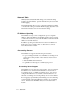
How Packets are Routed When the NETServer receives a packet, it looks up the packet’s destination in its routing table. If a static route is found, the packet is sent to the gateway listed. If a static route is not found, the NETServer will use a dynamic route. If the routing table contains no routes to the destination, it will send the packet to the Default Gateway. If no such gateway has been defined, the packet is discarded.
Incoming Packet Static (user defined) next hop in Routes Table? Routing Procedure No Listening for RIP Messages? No Yes Yes Yes Dynamic No route to destination No in Routes Table? Default Gateway (Next Hop) Defined? No Yes Connection to "Next Hop" Established? Yes Forward Packet to Next Hop No Next hop listed in Location Table? No Yes Trash Establish connection to next hop Packet TM NETServer/16 Destination X 6-8 LAN-to-LAN Routing
PAP/CHAP Authentication The NETServer supports auto-detecting the PAP and CHAP methods of login authentication on PPP connections. If a user dials in and starts sending PPP packets, the NETServer asks that the user log in with PAP (enter a user name and password). If the user refuses PAP authentication, the NETServer demands CHAP authentication. If this is also refused, the NETServer hangs up.
• A “challenge value” (a randomly generated string of characters) The challenged system then concatenates the challenge value with the shared secret and passes the new string through a hashing algorithm. When the hashing algorithm has formed a response based on this string, the challenged system replies with a packet containing both the response value and a user name.
A CHAP Challenge Example At the Corporate site is a NETServer with the Sysname of NETSERVE. A typical authentication might resemble the following: 1. A remote NETServer establishes a connection and negotiates for an authentication procedure. 2. NETSERVE becomes responsible for issuing a CHAP challenge. Inside that challenge is a User Name string containing the name NETSERVE and the random challenge string LASDFH;LASD. 3.
LAN-to-LAN Routing (Detailed Setup) The following section gives details on configuring routing from the command line. To attach to the command line software, see Connecting to the Command Line in Chapter 2. Configuring the Port Ports used for LAN-to-LAN routing need to be configured as Network ports. Step 1 - Port Type The port must be configured as a network port with one of the following options. Dial In, Dial Out, Dial In & Dial Out (twoway), or Hardwired.
Step 2 - Creating a Dial-Out Group Dialout and Twoway ports only. If the NETServer will dial out to a remote location, you must create a group of modems that can be used to dial out to the location. Note that you must do this even if only one modem will be used for that particular location. The following command creates such a group: set s group is any number from 0 to 99.
Adding a Remote Device to the Location Table This is required only if the NETServer will dial out to the remote location. If the NETServer will not be initiating connections to the remote location (the remote device will always do the dialing), you may skip to the section titled Adding a Remote Device to the User Table. Step 1 - Create a new location table entry. Use the following command: add location The Location Name can be up to 15 characters long.
Manual (Used for debugging) The NETServer dials out only when it receives a dial command from the command line. Continuous The NETServer will attempt to maintain the connection at all times. If the connection is broken it will dial again. Example: set location Atlanta on_demand Protocol Select the protocol to be used for the connection (PPP or SLIP). Use the following command: set location protocol IPX LAN-to-LAN routing requires the PPP protocol.
Netmask This is the remote network’s IP subnet mask. Use the following command: set location netmask MTU The Maximum Transmission Unit specifies the size of the largest packet that may be sent to this location. IPX connections will discard larger packets. IP connections will fragment larger packets prior to transmission. Normally, this should be set to the largest value that the remote network can handle.
Compression If using SLIP, enable Van Jacobson IP header compression only if both networks use CSLIP (compressed SLIP). If compression is enabled for a PPP connection, the NETServer will attempt to negotiate for compression, but will not use it if the remote site does not support compression. Use the following command: set location compression Dial Group Number Specifies which pool of modems will dial out to the remote location. Range is 0 to 99.
Step 3 - Multiple lines for a single connection When talking to other NETServers, the NETServer can spread a single TCP/IP connection over multiple lines (increasing throughput). Individual IPX clients/socket connections will show little (if any) benefit from this technique. However, because load balancing is employed, this technique may allow you to pipe more IPX clients/socket connections through the same bandwidth. There are two parameters used to set this up: High Water Mark and Maximum Ports.
Maximum Ports Sets the maximum number of ports the NETServer can use for a single connection to the remote location. Use the following command: set location maxports <0 .. 16> 0 (default) disable dialout to the location. 1 Use only one port for a connection. This setting must be used if the remote device is not another NETServer. 2+ When the number of bytes queued for the remote location exceeds the High Water Mark, another line will be added to the connection if it is available.
The second method is to configure each modem to dial a different stored number. This is done using the modem’s AT&Z command. You can send this command to the modem from the NETServer’s command line by typing the following: set s at “AT &Z=\r” is the position (0-9) in the modem’s non volatile memory (each modem stores up to ten numbers). Repeat for each modem in the dial group.
If you had configured this location to use multiple lines without a hunt group (see Step 3), you would configure the NETServer to use whichever number the modem has stored, rather than giving it the number explicitly. Since each modem has a different number stored, each will dial a different number. Example: set location Chicago script 1 “atds\r” “CONNECT” For detailed information on dial scripts, see Dial Scripts in Chapter 10.
Adding the Remote Device to the User Table Adding a user table entry is required if the remote device will be dialing into the NETServer. It is only required for dial out connections if you want to use CHAP authentication on a PPP connection. Step 1 - Create a User Table Entry Type in a user name and password: add netuser password Note: If you plan to use CHAP authentication, the password defined here is the CHAP shared secret. The shared secret must be the same on both devices.
Protocol Select the protocol to be used for the connection (PPP or SLIP). Use the following command: set user protocol IPX LAN-to-LAN routing requires the PPP protocol. If you have assigned an IPX Network Number, the NETServer will set this to PPP automatically.
Routing Set the level of RIP messaging that the two devices will exchange during the connection. Use the following command: set user routing broadcast Send dynamic routing information to the remote device. (but do not listen) listen Listen for dynamic routes received from the remote device. (but do not broadcast) on Do both of the above. off Do not send dynamic routing information. Ignore dynamic routes received.
LAN-to-LAN Routing Case Study The following example shows routing between two NETServers in order to demonstrate how each end of the connection would be configured. This case study assumes the following: • both NETServers (NETServerA and NETServerB) are configured with the correct IPX network number, IPX Frame Type, IP address and Netmask. • NETServerA’s Sysname is NSA. NETServerB’s Sysname is NSB.
This example will set up two NETServers for LAN-to-LAN routing. NETServer B will be configured to dial NETServer A on demand. In other words, when packets are waiting to be transferred, NETServer B will form a virtual connection to NETServer B. When the connection is no longer needed, it is terminated. Setting Up NETServer A NETServer A will use ports 7 and 8 to handle incoming routing from NETServer B.
Setting Up NETServer B NETServer B (a 16 port NETServer) will dial out to NETServer A using ports 10 and 11 (The port defaults will not work in this case). set s10 network dialout set s11 network dialout Instead of user entries, dial out ports have entries in the location table. In this case, a location entry for NETServer A. add location nsa (For CHAP, “nsa” is NETServer A’s Sysname) set location on_demand set location nsa destination 192.77.203.
Since this dial script expects the verbal result code “CONNECT” from the modem, we should make sure the the init script for each modem in the dial group contains Q0 and V1. The default init script, USR_int, contains both of these settings (as part of &F1) and some other useful modem configuration. So, we’ll just make sure that these modems are using USR_int. set s10 init USR_int set s11 init USR_int Since this is an on-demand connection, each modem should hang up if it’s not being used.
Testing the Connection You can test the connection by setting the location for manual dialing. set location nsb manual dial nsb -x The -x parameter lets you see the connection/authentication messages in order to verify the connection. Make any necessary changes to the dial script and retry dialing until the connection succeeds. Once the connection is successful, verify that the remote NETServer is accessible through your local network.
Connecting to NETServer A from NETServer B When a user on LAN2 tries to connect with a host on LAN1, NETServerB dials NETServerA and establishes a LAN-to-LAN connection. The first person to connect sees an initial delay while the NETServers exchange CHAP messages. After the initial connection, traffic will flow freely and any user on either network can use the connection to telnet, ftp, and so on back and forth. If there is no activity on the connection for 30 minutes, NETServerB hangs up.
Chapter 7 Talking to the Modems This chapter discusses use and configuration of the NETServer’s internal modems. The following subjects will be covered: • TCP/IP modem sharing • Modem Initialization Scripts • Sending AT commands to the modems TCP/IP Modem Sharing Configuring a port to act as a “host device” allows users on a local TCP/IP network to use the modem for dialing out.
can be any number not already used by the NETServer. We suggest 6000 plus the modem number. Assigning the same TCP port number to multiple ports will create a pool of modems. The user will be connected to the first available modem in the pool. Selecting NetData as the login service allows an application program to form a “Clear TCP” connection with a modem. In other words, data exchanged with the modem will not be filtered in any way.
Implementing Security with Host Device Dial Out To authenticate a host device dial out user, configure a host device port with a device service of Telnet and a TCP port number between 10,000 and 10,100. These ports can only be connected to by the NETServer itself, forcing the user to telnet to port 23, the default telnet port, and have the NETServer forward him to the modem. When the user connects to port 23, he or she will be prompted for a user name and password just like a login user.
Configuring modems as UNIX pseudo TTYs A pseudo tty device acts like a serial device, but is actually something else entirely. In this case, we would like one of the NETServer’s modems to act like it is connected to one of the serial ports of a UNIX host, even though it’s really attached to the NETServer. There are two different UNIX pseudo TTY device drivers that work with the NETServer. Both are available on the U.S. Robotics web site.
Keep in mind that other programs on the host may use these pseudo-tty devices, but usually select the pseudo-tty drivers from the beginning of the list (for example, /dev/ttyp0, /dev/ try, and so on). In order to avoid conflicts, we recommend you select the pseudo-tty device drivers from the end of the list (for example, /dev/ttypf or /dev/ttyqe).
Modem Initialization Scripts An initialization string may be sent to any one of the NETServer’s S-ports every time the port is reset (a modem resets itself each time it disconnects). An initialization string can contain any text that needs to be sent to a port at start up. For a modem, the initialization string will usually contain AT commands. There is no standard list of what commands a modem initialization string should execute. Every system administrator will have different needs for each modem.
Caution: Avoid using commands that write to the modem’s NVRAM (such as &W) in an initialization script that you plan to use indefinitely. Rewriting the NVRAM every time the port is reset may eventually wear the NVRAM out. Use such commands only on a short term basis. The following special characters are allowed.
Initialization Script Example Setting up a new initialization script is a four step process. The example given below forces modem 3 to auto answer. 1. Create an empty initialization script. add init auto_an 2. Define the contents of the new script. set init auto_an “ATS0=1\r\n” 3. Assign the new script to a port. set s3 init auto_an 4. Save the new configuration information. save all 5. Reset the port so your changes take effect.
Sending AT commands to the modems Version 3.1 of the NETServer/8 and NETServer/16 firmware allows you to send AT commands to the internal modems directly from the NETServer’s command line.
7-10 Talking to the Modems
Chapter 8 Packet Filters This chapter covers setting up packet filters for the NETServer. The following topics are included: • Filter overview • Creating new packet filters • Filter rule format • TCP/IP packet filtering • IPX packet filtering • Editing Packet filters Packet Filters Packet filters are primarily used in networks that cross organizational or corporate boundaries. They control inter-network data transmission by permitting or denying the passage of specific packets through network interfaces.
Types of Filters The NETServer supports the following types of packet filters: • Input and output filters; packet filters can be created to control either inbound or outbound data packets • Source and destination address filtering; a packet filter can permit or deny access based on the IP address of the source and/or destination • Protocol filtering; inbound or outbound network traffic can be evaluated based on the protocol • Source and destination port filtering; a packet filter can control what services l
Information Sources Internet packet filtering and security are complex issues which this chapter can barely scratch the surface of. The following sources provide additional information: Cheswick and Bellovin, Firewalls and Internet Security: Repelling the Wily Hacker, Addison Wesley, 1994, ISBN 0-201-63357-4 Siyan and Hare, Internet Firewalls and Network Security, New Riders Publishing, 1995, ISBN 1-56205-437-6 Input filters vs.
Adding Packet Filters 1. To create a new filter, type the following command: add filter The filter name can be up to 15 characters long. Optionally, you can add an extension beginning with a period to the end of a filter. For example, we recommend that you add .in to an input filter name (such as sales.in) and .out to the corresponding output filter (such as sales.out).
Input filters vs. Output filters You can assign two packet filters to each interface: an input filter and an output filter. Input filters control which packets are allowed into the NETServer through the interface. Output filters control what packets are allowed out of the NETServer. When possible, use the input filter to filter out an incoming packet rather than waiting to catch a packet on its way out of the NETServer. There are several good reasons for this.
Filter Rule Format A packet filter consists of a set of rules which you must create. A newly created packet filter contains no rules. The number of rules a packet filter may have is limited only by the amount of available flash memory in the NETServer. When entering rules at the command line, rules must be numbered. Rules are processed in order, starting at rule 1. There are three types of packet filter rules: IPX rules, IP rules, and SAP rules. A packet filter can contain all three types.
Rule Number This is a number up to the highest previously set Rule # plus one. For example, if a packet filter currently has four rules, the new rule can be any number between 1 and 5. Note that if an existing rule number is specified, it is replaced by the new rule. If no parameters are specified for the rule, that rule is deleted. Permit or Deny This is a required parameter which indicates whether the packets meeting the specified criteria should be forwarded (permit) or discarded (deny).
TCP/IP packet filtering After the filter name, rule number and permit/deny, IP rules start with the following parameters: Depending on the protocol, there can be more options following these parameters. See TCP and UDP parameters and Filtering ICMP packets (below) for more information. Source Address The address given here is compared to the source address of the packet.
Destination Address The address given here is compared to the destination address of the packet. Note that only the part of the address specified by the mask field is used in the comparison. If a match is found, the packet is forwarded (rules containing permit) or discarded (rules containing deny). The following rule example denies destination addresses that match the first 8 bits of the given IP address (that is, addresses beginning with 192): deny 0.0.0.0/0 192.77.200.
TCP and UDP parameters TCP and UDP packets can be filtered by source and destination socket numbers. This allows you permit or deny specific services. src Compare the source port number in a TCP or UDP packet to a specific value.
Standard Port Numbers The table below contains information on standard port numbers for some common services. For a complete list, see the most recent “Assigned Numbers” RFC (currently RFC 1700).
TCP UDP Description 518 518 ntalk (new terminal chat) - 520 RIP 540 540 uucp (UNIX to UNIX copy) 540 540 uucp-rlogin 543 543 klogin (Kerberized login) 1642 - PortMux daemon - 1645 RADIUS security - 1646 RADIUS accounting Filtering RIP messages If the NETServer is listening for or broadcasting RIP messages, you should permit them (UDP dst eq 520) to pass in the appropriate direction(s). Note that spurious RIP messages can disrupt your routing tables.
Step 2 - The client opens a control channel To initiate an FTP session, the client opens a control channel on the well-known FTP port 21. This means any client on the local network must be able to send packets to TCP port 21 on any external host. set filter ftp.out 1 permit 192.77.203.0/24 0.0.0.0/0 tcp dst eq 21 Step 3 - The host must reply Allow packets coming from port 21 on any external host.
FTP Example 2 If you also wanted to allow external clients access to a specific FTP server on your network, you could add a few more rules. In this example, our FTP server is 192.77.203.12 set filter ftp.in 3 permit 0.0.0.0/0 192.77.203.12/32 tcp dst eq 21 set filter ftp.out 3 permit 192.77.203.12/32 0.0.0.0/0 tcp src eq 21 dst gt 1023 established set filter ftp.out 4 permit 192.77.203.12/32 0.0.0.0/0 tcp src eq 20 dst gt 1023 set filter ftp.in 4 permit 0.0.0.0/0 192.77.203.
Filtering ICMP packets ICMP packets can only be filtered by type. So, the only option is: type The ICMP message types are listed below.
IPX packet filtering IPX packets can be filtered by source and destination host, network or socket. Additionally, SAP packets can be specifically permitted or denied. Note that IPX network numbers must be specified as 8-digit hex values. Node addresses must consist of the 8-digit network number, followed by a colon and then the 12-digit MAC address. IPX Rules The IPX rule format is as follows: may be srcnet, dstnet, srchost, dsthost, srcsocket, or dstsocket.
dsthost Compare the destination IPX node address contained in the packet to the address given. The IPX address should be in hexadecimal format. dsthost srcsocket Compare the source IPX socket number contained in the packet to the socket number given. You must specify the type of the comparison. Valid comparisons are: less than (lt), equal (eq), or greater than (gt).
SAP Rule Options SAP rules are only used in output filters. The rule format is as follows: Possible keywords are server, network, host, and socket. server Compare the server name of an advertised service to the server name of the packet filter. server network Compare the IPX network number of the advertised service to the network IPX address. The IPX network number must be in hexadecimal format.
Editing Packet Filters Edit a Packet Filter See Filter Rule Format, earlier in the chapter for a description of filter rule format. For information on filter rule options, see the section specific to the type of packet filter you are editing. To edit a filter, replace an existing rule with a new one.
View a Packet Filter If you want to check to view a specific packet filter, use the following command: show filter You’ll see the packet filter’s IP rules first, IPX rules second, and then the SAP rules. The information you see might look something like this: 1 deny 0.0.0.0/0 0.0.0.0/0 tcp src eq 23 2 deny 0.0.0.0/0 0.0.0.
Chapter 9 Administrative Tools This chapter covers commands whose functions are purely administrative. • Configuring the !root account • Manually connecting to a remote site • Troubleshooting commands • The SHOW command Configuring the !root account The commands in this section control access to the supervisor account (!root).
Note: You can also disable Telnet access to the !root account. For more information, see Telnet Access Port below. Telnet Access Port You can reach the command line interface by initiating a Telnet session and logging into the NETServer as !root. The Telnet Access Port identifies the specific TCP port number that the NETServer should listen to for incoming Telnet sessions. The default is 23, Telnet’s well-known port number. The Telnet Access port number can range from 1 to 65536.
Manually Connecting to a Remote Site You can dial a remote (or local) site from the Command Line software with the dial command and log in to a local host with the nslogin, rlogin, and telnet commands. The Dial Command Use the following command: dial must be a valid Location Table entry. You can also add a debugging option, -x, after the field. This option displays the negotiation/connection messages.
Troubleshooting Commands Troubleshooting commands are described in the following sections. Viewing DEBUG messages The debug command allows you to view certain messages which would normally be discarded. If you have a strong background in the protocols you wish to view, these messages should be useful in determining the following: • Why a dial in user is failing to connect. • Whether they are negotiating PAP or CHAP. • What their final IP address and netmask are.
4. When you are finished viewing debug messages, tell the NETServer not to display messages. set debug 0x00 5.
Ifconfig This command displays the current (active) configuration of an interface. Note that the configuration of a serial port is only displayed when there is an established point-to-point connection using that serial port. That is, an established connection with S1 would show up as ptp1 (point-to-point connection 1) Ifconfig also lets you reconfigure the NETServer interfaces while they are active. Note that this affects configuration for the currently active connection only.
The second line contains the following information: Broadcast The Ethernet broadcast address. Dest Displays the IP address of the device on the other end of a point-to-point connection. Inet The interface’s IP address (NETServer employs its LAN port IP address for most connections). IPXframe The IPX frame type or protocol. IPXnet The IPX network address of the frame type MTU The maximum transmission unit of the interface. Netmask The IP subnet mask the interface is currently using.
Ping This verifies that the NETServer can communicate with other devices on the network. Use the following command: ping is the IP address or name of the device on the network you want to ping. You’ll see the following results if the ping is successful: 199.55.55.55 is alive If you have a name service such as DNS or NIS, you may see the following: sales_east (199.55.55.55) is alive If the ping is unsuccessful, you’ll see the following: No answer from 199.55.55.
Ptrace This command lets you monitor network traffic at the packet level. Use the following command: ptrace Note that if you type the command without specifying a packet filter, ptrace is disabled. Keep in mind that this packet filter does not function like an output or input packet filter. It does not discard packets that do not meet its rules, it simply reports on those packets which do meet its criteria.
Traceroute This command identifies the routers (and the path) to a remote host/system. The name or IP address of the remote host/ system follow the traceroute command. Use the following command: traceroute The information you see might look something like this: Command> traceroute 192.77.204.1 traceroute to (192.77.204.1), 30 hops max 1 192.77.203.1 Version Use this command to see what version of NETServer code your NETServer is using. U.S.
The SHOW command The show command can be used to view the NETServer’s current configuration and its routing activity. The command has the following options: show...
show arp Show arp allows you to view IP address resolution information for the given interface. To use this command, type show arp can be one of the following: net0 The LAN port ptp A point to point connection on port S The NETServer will respond with a list of IP addresses, followed by the corresponding MAC addresses. Each response is similar to the following: 192.77.206.
show memory Use the following command to see the NETServer’s DRAM memory utilization: show memory The information you see might look something like this: System memory 2097152 bytes - 1457952 used, 639200 available Free blocks (block_size:count): 4096:1 1152:0 640:0 80:7 160:1 48:5 128:0 32:8 System nbufs 800 created - 20 used, 780 available (27 maximum used, 0 underflows) System netqueues 174 available, 172 min.
Foreign Address The address of the port on the remote side of a point-to-point connection. IPX port addresses appear as 00000000.0. (State) The status of the connection. Possible values include SPX LISTEN, UDP, and LISTEN. show netstat The show netstat command provides information on network statistics, specifically on each network interface or ptp (point-topoint) connection.
show sap Use the following command to view the SAP interfaces: show sap The information you see might look something like this: Server ------------PRINTERS AE_311 Svc ----47 4 Network Host Sock ------------------------------------------0AE31100:000000000001:8060 0AE31100:000000000001:0451 Hops ------3 2 Interface -----------net0 net0 show sessions This command provides a port-by-port synopsis of activity, including information such as the user currently dialed in, the destination host system, the type
Type 9-16 This is the type of service that the port has been configured to support. Possible Port Types are: Login User login port Device Host device port Twoway Both user login and host device port Netwrk Network (dial in or dial out) port Dir The direction associated with the port type. For example, a network dial in port will have a direction of In, and a Twoway port will have a direction of I/O.
Chapter 10 Command Reference This chapter contains a complete listing of all the commands for configuring the following (in alphabetical order): • Global Configuration • The Hosts Table • The Location Table • Net0 (LAN Port) Configuration • The Netmasks Table • The Ports Table (S-Port Configuration) • The Routes Table • SNMP Setup • The User Table Global Configuration Global Configuration includes commands that affect every user and every port.
How to . . . Get help To bring up a list of command options for Global Configuration, use the following command: help set global Save Changes To save any configuration changes you have made, use the following command: save global View the Global Configuration Table To view Global Configuration, type: show global The information you see might look something like this: System Name: Cincinnati Default Hosts: 192.77.203.54 192.77.203.65 192.77.203.55 IP Gateway: 192.77.203.
Global user parameters The following parameters apply to all users in the user table. Assigned Address Optional. The Assigned Address is the first of 9 (NETServer/8) or 17 (NETServer/16) consecutive IP addresses. One address is set aside for each modem plus an additional address for the external serial port (s0). Network users whose IP address field are set to “assigned” are given one of these IP addresses when they dial in to the NETServer.
Randomize Hosts This command is used to relieve the burden on frequently-used global default, port default and RADIUS user table hosts. All three of these tables contain a default host and several alternate hosts. When the random host command is turned off (default), the user will be connected first to the default host. If the default host is unavailable, he or she will be passed onto the first alternate host that is available.
Global routing parameters The parameters in this section configure routing on all ports. Default Gateways If the NETServer does not know where to send a packet, it forwards the packet to the default gateway or router defined in this step. Default gateways must be on the same subnet as the NETServer. You must also enter a metric (hop count) for each type of default gateway. Possible values range from 1 (default) to 15.
Default Route This command determines whether the NETServer will dynamically update IP default gateway information. The default is off. Use the following command: set default On The NETServer will broadcast its default gateway information as part of normal RIP messaging and will also listen for default gateways broadcast by other routing devices.
NetBIOS Packet Propagation On an IPX network, NetBIOS obtains information by broadcasting type 20 packets to all networks. In order to fully support NetBIOS over IPX, the NETServer must be configured to forward type 20 broadcast packets across an IPX network. The following command is used: set netbios The default is off, which disables NetBIOS packet propagation.
Name Service These commands configure the name service your network uses. A name service allows you to use host names rather than just IP addresses. The default is no name service. If you select a name service, you must also enter a Name Server and a Domain Name (see below). Service The choices for name service are DNS and NIS, with DNS being the default. DNS The network uses the Domain Name Service (DNS). NIS The network uses the Network Information Service (NIS).
Domain name This is the name of the domain the NETServer belongs to. Both the primary and the secondary name servers must belong to the same domain. Use the following command: set domain DNS Cache Reset Time-out Once the NETServer has obtained a name resolution response from a DNS server, it caches the results so that the name resolution information can be reused without further DNS requests.
RADIUS security The following commands configure the NETServer’s use of RADIUS security servers. See Appendix F for more information on RADIUS. Primary RADIUS Server This is the IP address of the primary RADIUS authentication server. Use the following command: set authentic Alternate RADIUS Server The IP address of the secondary RADIUS authentication server. If the primary server is unavailable, the NETServer will check with this server.
Accounting servers The following commands configure the NETServer’s communications with accounting servers. RADIUS Accounting This command specifies the primary (1) and secondary (2) RADIUS accounting servers. RADIUS is an open protocol for network accounting. This allows the NETServer to send accounting messages to any one of a number of RADIUS implementations available, including U.S. Robotics’ own RADIUS server. The default for both the primary and secondary accounting server is 0.0.0.0 (none).
ICMP Logging This command determines whether the NETServer sends ICMP errors such as Host Unreachable to the Syslog server. The default is off, which means that the NETServer does not pass such messages to Syslog. set icmplogging Note that the NETServer must be configured to use Syslog network accounting (see Syslog Accounting).
Hosts Table Like a name service, the hosts table translates names to IP addresses and vice versa. However, the hosts table is only used by the NETServer itself, rather than the entire network. If you are not using a name service and you want to use names rather than IP addresses, you must first create host table entries for all the hosts you want to refer to. How to . . .
Location Table Use the location table to define sites that the NETServer can dial out to. (As opposed to dialing in, which requires a User Table entry). How To . . . Add a Location to the Location Table To add a remote site or host to the Location Table, use the following command: add location The Location Name is case sensitive and can be up to 15 characters long. Sales and sales would be two different locations.
Save Location Table Changes To save changes you have made, use the following command: save location View the Location Table To view the Location Table, type the following command: show table location The information you see might look something like this: Location ————— sasha net Destination ——————— 199.77.203.15 192.77.206.3 Netmask —————— 255.255.255.0 255.255.255.
Location Table Parameters Connection Type This determines when then the NETServer will dial the remote host or site. Your options are Continuous, Manual, and On Demand. The default is On Demand. Continuous The NETServer keeps the connection to the remote site active at all times. If the connection is broken for any reason, the NETServer automatically tries to reconnect.
IP Address This command is used to tell the NETServer what IP address will be used by the remote device. The default is 0.0.0.0., which disables the port for TCP/IP connections using PPP. Use the following command. set location destination PPP links: If the IP Destination is set to 255.255.255.255, the NETServer will try to negotiate or learn the location’s IP address. This will work only with manual and continuous connection types.
Protocol Default is SLIP. This field indicates what protocol the NETServer should use to encapsulate packets bound for the remote user. set location protocol Connections that forward IPX packets must use the PPP protocol. If you enter an IPX network number for the location, the NETServer will set this to PPP for you. Routing This field controls RIP messaging between the NETServer and the remote site.
Dial Group This field specifies which group of modems will dial-out to a remote location. Group numbers can range from 0 to 99. The default group, 0, can be thought of as the group of all modems which have not been assigned to a different group. set location group Specifying a modem group lets you reserve a modem for dialing specific locations, or ensure that the modem used for a connection is configured correctly for this location.
Idle Time-out Applies to Manual and On Demand locations only. Idletime specifies how many minutes a dial out connection to this location can remain idle before the NETServer disconnects. Default is 0 (disable idle time-out). Use the following command: set location idletime <2 to 240 minutes> Note: The idle timer ignores RIP, SAP and keepalive packets, allowing ports to time-out even though these protocols are running.
MTU This is the Maximum Transmission Unit (MTU) used with this interface. MTU sets the largest frame or packet size that a connection protocol will send. If an IP packet’s size is greater than the MTU setting, it’s broken down into smaller pieces. IPX packets larger than the MTU are discarded. Use the following command: set location mtu For IPX connections, the MTU must be set to 1500. PPP connections are set between 100 and 1500 (default is 1500).
Output Filter Packets being sent to the remote location are evaluated against this filter and are discarded or accepted accordingly. See Chapter 8 for more information on packet filters. Use the following command: set location ofilter Input Filter Packets received from the remote location are evaluated against this filter and are discarded or accepted accordingly. See Chapter 8 for more information on packet filters.
Special Characters The send or reply strings can contain any printing ASCII character. Also, you may use the following special characters: \r ASCII carriage return \n ASCII line feed \0XX octal digit XX (such as \O7) \\ single backslash (\) “” An empty reply string (expect no reply) The Last String in a Dial Script The last entry in the Dial Command Script must be a Reply string that indicates that the remote location is ready to begin receiving network packets.
LAN Port (Net0) Configuration LAN port configuration lets you configure the NETServer’s Ethernet interface. If you have changed the IP address or IPX network number, you must reboot the NETServer after you save your changes. How to . . .
View LAN Port Configuration Use the following command: show net0 The information you see might look something like this: Ethernet Status: IP - Enabled IPX - Enabled Ethernet Address: Ethernet Media: 00:C0:49:00:45:43 Autodetect Interface Addr: Netmask Broadcast Address: 192.77.203.55 255.255.255.0 192.77.203.
Configured Ethernet Media Previous versions of the NETServer firmware automatically detected which type of Ethernet cable was connected to the NIC. Although convenient, auto-detection has two disadvantages: • There is a slight delay at boot time (while auto-detection takes place). • If you don’t attach an Ethernet cable to any of the interfaces, lights flash at you and you get a lot of annoying messages in debug mode. NETServer now allows you to specify what type of cable is being used.
Netmask This is the IP subnet mask of the subnet attached to the NETServer’s LAN interface. The default is 255.255.255.0, which would be appropriate for a Class C network with no subnetting or for Class C size subnets of larger networks. You must change this value if the local network is using a different subnet mask. Use the following command: set net0 netmask Broadcast Address This field sets the IP address that the NETServer uses as the local broadcast address.
IPX Frame Type This sets the IPX frame type for the NETServer’s LAN interface. The default is 802.2 Ethernet. If the network attached to the NETServer’s LAN interface has more than one frame type, choose the frame type that best suits your network. Keep in mind that this frame type has a specific network number associated with it. When you enter the IPX Network Number for the Net0 interface, you must use the number associated with this frame type.
Input Filter This filter controls packets coming into the NETServer through the LAN interface. Use the following command: set net0 ifilter Packet filters control access to computers, networks, and network services by using a set of rules to analyze the header information of each packet of data received. If the packet meets the filter’s criteria, it is allowed to pass through. Otherwise, the packet is discarded. See Chapter 8 for instructions on creating packet filters.
Netmask Table The netmask table is used to define netmasks for Supernetting (Classless InterDomain Routing). See Appendix B for an explanation of this technique. Alternatively, the netmasks table could be used to force the NETServer to advertise routes to individual hosts on that network rather than a single route to the entire network. To do this, assign the desired network a netmask of 255.255.255.255. How to...
Ports Table (S-port configuration) The S-Port table is used to configure the external serial port and all the internal serial ports (modem ports). How to . . .
When a NETServer reboots, it copies configuration data from the permanent configuration saved in flash memory to the default configuration work area. The port is then reset, which makes that configuration active. You can change the permanent configuration by issuing one of the following commands, which copy the default configuration to flash memory: save s save all View the Ports Table To view all of the S-ports, use the following command: show all Local Addr:192.77.206.57 Gateway: 0.0.0.
Host This column displays IP addresses. The address displayed is dependent on what kind of connection currently exists on the port. active login user The address of the host the user is connected to active network user The address of the user host device session The address of the host accessing the modem idle login port The address of the port's default host If none of the above is true, this field displays nothing. Type The port type.
View an Individual Port To view a specific port, use the following command: show s The information that appears may look something like this: Status: Input: Output: Pending: Command 964 17606 0 Active Configuration ————————————— Port Type: User Login Login Service: NetData Baud Rates: 115200 Databits: 8 Stop bits: 1 Parity: None Flow Control: None Modem Control: Off Init Script: USR_int Init When?: Every Reset Hosts: Erie Terminal Type: Login Prompt: Dial Group: Parity Errors: Framing Errors: Ov
Determining a Port’s Type Three settings determine what type of connection a port permits: User Login, Host Device and Network. The different port types are discussed below. The default settings for a port are User Login enabled, Host Device disabled, and Network set to Dial In. This means that the port may be used for login sessions using a terminal service such as Telnet or for dial in PPP or SLIP connections, but may not be used to dial out.
You can find these drivers (daemons called nettty and in.pmd) on the U.S. Robotics web site. To configure a port for Host Device use, set s device /dev/ If you are using a UNIX pseudo TTY driver in conjunction with the host device setting, the field must contain the name of the pseudo TTY device being used. See Chapter 7 for more information on using such a driver. If you are not using a pseudo TTY driver, this field should contain the word network.
Network The Network field determines if the port permits PPP or SLIP connections. You may also enable User Login and Host Device (unless Network is set to Hardwired). The default is Dial In. Use the following command: set s network Dial In Remote users may dial in to the NETServer and establish a PPP or SLIP connection with the local network.
Specifying a dial group lets you reserve a modem for dial-up to specific locations, or ensure that the modem used to make the connection is configured as this particular location requires. Dial In Port Parameters These parameters apply to both user login and network dial in ports. Idle Time-out This field specifies how many minutes the line can remain idle before the NETServer disconnects.
The Login Message can be up to 240 characters in length. Use the carat ( ^ ) to designate the start of a new line. Login Prompt Optional. The following command allows you to customize the login prompt for the port. Any valid ASCII characters may be entered: set s prompt If you use quotation marks when you enter this string (either as delimiters or as punctuation), they will appear in the prompt string. The default for Network Dial In ports is simply login.
IMPORTANT: Without a user table entry, the NETServer can’t tell what type of user is dialing in. If security is off, network users who are not part of the User Table are assumed to be login users and passed on to a host. Security should be on if network dial in users will be using the port. User Login Port Parameters The following parameters apply only to user login ports.
Host This is the host for users whose user table host is set to Default. If security for the port is off, this is also the host for users who do not have user table entries. set s host Default The port uses the Default Host specified in the Global Configuration Table. Prompt When users dial in, the port displays a host prompt. Users then type in the name or IP address of the host they want to connect with. The login prompt for that host appears next.
Login Service The NETServer uses the service specified here to connect users not in the user table to the port default host. Users with user table entries will not use this setting. This setting will never be used if security is set to on. The Default login service for a port is PortMux. Note that this is different from the default for an individual user (Telnet).
Netdata Unlike Telnet, Rlogin, and PortMux, Netdata is not actually a login service. Netdata is a direct (clear TCP) connection to a given TCP port number. 8-bit data is exchanged without interpretation. Such connections may be used by dial in applications that require a socket interface. Terminal Type This is required only if Login Service is set to Rlogin. Telnet will use this information if it is provided or default to dumb terminal mode if it is not provided.
Hardwired Port Parameters The parameters described below apply to port s0 if it has been configured as network hardwired. Compression This indicates whether Van Jacobson TCP/IP header compression is enabled (on) or disabled (off). The default is off. Use the following command: set s0 compression IP Address This is the IP address of the remote system. Use the following command: set s0 address If the destination is set to 255.255.255.
PPP connections are set between 100 and 1500 (default 1500). SLIP connections are set between 100 and 1006 (default 1006). Netmask This is the remote network’s IP subnet mask. The default is 255.255.255.0, which would be appropriate for a Class C network with no subnetting or for Class C size subnets of larger networks. You must change this value if the local network is using a different subnet mask.
For example to escape the ASCII null character, the command would be set s0 map 00000001 The default is 00000000 (do not escape any characters). We recommend that you do not change this field unless specifically required by your network. Protocol This field indicates what protocol the NETServer should use to encapsulate packets going across the hardwired serial connection.
Serial Communications Parameters The following parameters configure the connection between the NETServer and the devices attached to its ports (modems). These parameters are independent of port type (such as user login and network dial in) S0 only: Setting DIP switch 3 on (down) will override these settings and force the following: Port Type: Login Baud: As configured by DIP switches 1 and 2 Byte Format: 8/N/1 Modem Control: Off Port Speed This is the baud rate of the port.
Parity This is the parity of the data. The default is none. set s parity Flow Control This is the type of flow control used by the port. Note that you will also have to configure the modem to use this type of flow control. Use the following command: set s XON/XOFF Sets the port to software flow control. ASCII control characters stop and start the flow of data. Not Recommended. CTS/RTS Sets the port to hardware flow control.
Routes Table Configuration The routes table contains both static and dynamic routing information. Dynamic routes are updated by RIP broadcasts received from other routing devices on the network. Static routes are routes added to the table by hand. A static route to a given location will override any dynamic routes to the same location. Static routes are required when dynamic routes to a given location are not being received (For example, when RIP is not running). How to . . .
Delete a Routes Table Entry To delete an IP route, use the following command: delete route To delete an IPX route, use the following command: delete ipxroute Save Routes Table Changes Use the following command for IP routes: save routes Use the following command for the IPX routes table: save ipxroutes View the IP Routes Table Use the following command to view the IP routes table: show routes The information you see might look something like this: Destination ——————— 192.77.
Viewing the IPX Routes Table To view the IPX Routes Table, use the following command: show ipxroutes The information you see might look something like this: Network ————— 00071557 AE401211 AE401207 0AE31E11 0AE31E02 0AE31E03 Gateway ————————————— 0AE31E03:0000C0BDA15F 0AE31E03:0000C0BDA15F 0AE31E03:0000C0BDA15F 0AE31E03:0000C0BDA15F 0AE31E03:0000C0BDA15F 0AE31E03:00C04900311D Flag —— ND ND ND ND ND NL Met —— 2 2 2 2 2 1 Ticks —— 2 2 2 2 2 1 Interface ———— Net0 Net0 Net0 Net0 Net0 Net0 Flag Parameter
IP Parameters Destination This is the IP address or name of the host or network to which the NETServer needs to send packets. Gateway This is the IP address of the host through which packets should be forwarded to reach the above destination. Metric This is the hop-count or the number of gateways that information must pass through before reaching the destination. Interface This is the chassis interface through which the destination can be reached.
IPX Parameters Destination This is the IPX network number of the network to which the NETServer needs to send packets. Network This is the network node address of the gateway, bridge or router the packets will be forwarded through in order to reach the destination. The format for the network node address is an eight digit hexadecimal address followed by a colon and then a 12 digit hexadecimal address. For example: 0200053B:00005892AF32.
SNMP Table The NETServer provides support for using the Simple Network Management Protocol (SNMP) and supports industry standard MIB-II variables. These variables are fully described in your MIB-II documentation. How to . . .
View SNMP Table To view the SNMP settings, use the following command: show table snmp The information you see might look something like this: SNMP Readers (public): Any SNMP Writers (private): Any SNMP Table Parameters Read Community Name The SNMP read community is a kind of password. Only devices that know the correct Read Community Name may read the NETServer’s MIB information. The default is public.
Read Hosts This defines which host(s) can perform SNMP GET operations on the NETServer MIB objects. Use the following command: add snmphost reader Valid options are: Any Any host with the correct read community may retrieve SNMP data from the NETServer. None The NETServer will not respond to any attempts to retrieve SNMP data. IP Address A specific host may read SNMP data from the NETServer.
User Table The User Table defines users who dial in to the local network to become virtual nodes or to establish login sessions with local hosts. How to . . . Add a User to the User Table The user name can be up to 8 characters long, and the password can be up to 15 characters long. Both user name and user password are case-sensitive. You cannot have both a login user and a network user with exactly the same user name. For example, a login user and a network user cannot both have the name Bob.
Change a User’s Parameter(s) To change a user’s parameters, use the following command: set user
The information displayed for a network user might look something like this: Username: Address: IPX Network: Protocol: MTU: Ed Negotiated 00000022 PPP 1500 Type: Netmask: Dial-In Network User 255.255.255.0 Options: Asynch map: Listen, Compression 00000000 Login User Parameters Access Filter The packet filter specified here determines which hosts this user is allowed to establish sessions with (useful when Host is set to Prompt).
Host This field defines which network host the user’s session is forwarded to. Use the following command: set user host Default Consult the ports table to obtain the default host for the port the user has dialed into and connect the user to the host listed there. Prompt Allow the user to select a host (either by IP address or name) to begin a login session. IP address Connect the user to the host whose address is entered here.
Netdata Unlike Telnet, Rlogin and PortMux, Netdata is not actually a login service. Netdata is a direct (clear TCP) connection to a given TCP port number. 8-bit data is exchanged without interpretation. Such connections may be used by dial in applications that require a socket interface.
Network User Parameters Dialback This is the location that the NETServer will dial after verifying the user’s name and password. It must be a valid location in the Location Table. Use the following command: set user dialback IP Address This is the IP address that the user has for the duration of the connection.
Protocol Default is SLIP. This is the protocol the NETServer should use to encapsulate packets bound for the user. set user protocol IPX connections require the PPP protocol. PPP Async Map The PPP protocol supports the escaping of non-printing ASCII characters. Escaping means that specific characters won’t be sent, but will be replaced by a special set of characters. The remote site then interprets this special set of characters as the original characters.
Routing Default is off. This determines whether the NETServer exchanges routing information (RIP messages) with the dial in user. Use the following command: set user routing On The NETServer sends RIP information to the dial in user and listens for dynamic routes received from the dial in user. Broadcast The NETServer sends RIP information to the dial in user, but does not listen for dynamic routes received from the user.
Output Filter Optional. This is a packet filter that screens all packets sent to the user. See Chapter 8 for more information on packet filters.
10-66 Command Reference
Appendix A Technical Specifications 8 and 16 port NETServer Hardware Certification Complies with FCC Part 15 and Part 68, UL-listed, CSAapproved Processor 486SX at 33 MHz Operational MemoryDRAM (Dynamic Random Access Memory) 4 Megabytes Flash ROM 2 Megabytes Physical Dimensions 12.6 x 17.5 x 3.5 inches 32.0 x 44.5 x 8.
Environment Shipping and Storage Temperature: -25° to +75° Celsius, -13° to +167° Fahrenheit Relative Humidity: 0 to 100% non-condensing Operating Temperature: 0° to +40° Celsius, 32° to +104° Fahrenheit Relative Humidity: 0 to 95% non-condensing Power Requirements AC PSU Nominal 120V (90-264 VAC) @ 47-63 Hz Maximum Output Power 125 watts +5 V 18 A +12 V 1.9 A -12 V 1A Maximum Input Power 160 watts 1.3 A Typical Input Power 8 port 57 watts 0.5 A 16 port 104 watts 0.
External Serial Port (“Console”) 8-Position Modular Jack Circuit Function Direction 1 2 3 4 5 6 7 CC CF CD AB BB BA CB Data Set Ready Carrier Detect Data Terminal Ready Signal Ground Receive Data Transmit Data Clear to Send Inbound Inbound Outbound Inbound Outbound Inbound 8 CA Request to Send Outbound Electrical specification: Connectors: RS-232, 8-position modular jack 8-position modular jack: Stewart 88-360808 or equivalent DB-25: Amp 748677-1 or equivalent Configuration: DTE Transmissi
Nominal direct current resistance: Center conductor: 24 gage (7 strands 32 gage); .61 millimeter diameter; 23.7 ohms/1000 feet; 77.8 ohms/kilometer Shield: 15.5 ohms/1000 feet; 50.9 ohms/kilometer Nominal outside diameter: .265 inch; 6.
Connector: 8-position modular jack, Stewart 88360808 or equivalent Cable Specifications Wire Type: .5mm or 24 AWG twisted pairs Maximum Cable Length: 100 meters (328 ft.) with standard receiver squelch levels Cable Loss: Must be ≤ 11.5 dB/100 m for frequency range of 5-10 MHz Characteristic Impedance 85-111 Ohms for frequency range of 5-10 MHz Propagation Delay: ≤ 5.
Cable Specifications Wire Type: Coaxial center conductor .89 ± .05 mm diameter stranded, tinned copper Shield 2.95 ± .15 mm inside diameter dielectric solid preferred; any other material that meets other cable specs polyvinyl chloride with outer diameter of 4.9 ± .3 mm jacket - or fluoropolymer with outer diameter of 4.8 ± .3 mm Maximum Cable Distance: 185 m DC Loop Resistance: ≤ 50 milliohms/meter Velocity of Propagation: .65c Characteristic Impedance: 50 ± 2 Ohms Attenuation: ≤ 8.
Token Ring Network Interface Card STP Connector Token Ring Data Transfer Rate: 4 or 16 Mbps Accessing Scheme: Token Passing Topology: Star Wired Ring Maximum Nodes for Physical Network: 250 Transmission Medium: Type 1Individual Shielded Pair Network Lobe Distance: 100 meters (328 ft.
UTP Connector Token Ring Data Transfer Rate: 4 or 16 Mbps (megabits per second) Accessing Scheme: Token Passing Topology: Star Wired Ring Maximum Nodes 72 for Physical Network: Transmission Medium: Type 3Unshielded Twisted Pair Network Lobe Distance: 100 meters (328 ft.
NETServer Firmware Specifications Routing Support Transparent On-Demand routing IP and IPX protocol routing Inverse multiplexing with programmable load balancing Host, subnet, and network routes supported Selective default routing Continuous connection (automatic retries after connection loss) Scheduled Link Establishment from UNIX cron Administration Local FLASH ROM for booting & configuration storage Alternate tftp boot Support for Domain Name Service (DNS) Support for Network Information Service (NIS) C
PPP Specific Features Address and control field compression Protocol field compression PAP and CHAP authentication protocols Magic number loopback detection Maximum receive unit negotiation Async control character map negotiation IP Address negotiation and assignment Van Jacobson compression TCP/IP headers Industry Standards Support TCP/IP (Transmission Control Protocol/Internet Protocol) RIP (Routing Information Protocol) SLIP (Serial Line Internet Protocol) and CSLIP (Compressed SLIP) ICMP (Internet Cont
SLIP and PPP Client Software Support Novell LAN WorkPlace TCP/IP NetManage Chameleon Sun PC/NFS FTP PC/TCP Windows ‘95 Stampede 3.
A-12 Technical Specifications
Appendix B Addressing Schemes This appendix contains a brief introduction to the IP and IPX addressing schemes for administrators that are new to either one or both. IPX Addressing Basics Unlike TCP/IP, Novell’s IPX protocol uses two separate address fields for each network interface: a 4 octet (4 byte) network number and a 6 octet node address. The complete 10 octet address is traditionally written as two hexadecimal numbers separated by a colon, for example: 001EF230:000000012A45.
These 32 bits are structured very differently from IPX addresses, in which you always have an 8 hex digit network number followed by a 12 hex digit node address. Address Classes In IP, the same 32 bits can be divided in a number of different ways to indicate networks and subnetworks of different sizes. Imagine what would happen if the colon in the middle of an IPX address could slide left or right in the address.
For example, a netmask of 255.255.255.0 on a Class B network would indicate that the network is divided into 254 subnetworks of 254 nodes each (0 and 255 are reserved numbers). 128.5.63.28 would be host 28 on subnetwork 63 of that network. The network itself would be called 128.5.0.0 (Class B network number 5). Notice that by using subnet masks, you can define a natural hierarchy in which the addresses themselves indicate how a packet is to be routed.
Two important things must be noticed about the address divisions created by a subnet mask. 1. RFC 950 requires that the first and last subnet created by a mask are reserved. So, the number of usable subnets is always 2 less than the number of divisions created. This makes 128 an unusable netmask because it has no legal subnets! 2. The first and last host address in each subnet are also reserved (see Reserved Addresses below).
Supernetting (Advanced TCP/IP) Because Class B Internet addresses are in short supply, larger networks are now usually granted a contiguous block of several Class C addresses. Unfortunately, this creates very large routing tables since multiple Class C routes have to be defined for each network containing more than 254 nodes. Larger routing tables mean more work for the routers and, therefore, poorer performance.
CIDR - Each Supernet is treated as a single entity Since supernet addressing is a fairly complex mechanism, the easiest way to understand it is to walk through the setup process. Step 1 - Select a netmask for each supernet Each supernet must have a netmask assigned to it. The netmask for an individual supernet can be, but does not have to be, the same as the netmask for any other supernet.
Notice that the number of zero bits in the third octet will actually dictate the number of Class C networks in the supernet. Each zero bit makes the supernet twice as large. So, a supernet composed of 8 Class C networks would actually have 3 zeroes (8 = 23). This would seem very limited since it restricts you to using groups that nicely fit into a power of 2 (1, 2, 4, 8, 16...).
Step two - Select a range of addresses for each supernet The range of addresses in a supernet must fit exactly into a space that can be described by its netmask. This means that the zero bits in the netmask must also appear in the first address of the supernet block. For this to be true, the third octet in the address must be an even multiple of the same power of 2 used to form the netmask.
Supernet Example The four networks in the example below are all connected to the same Internet service provider (ISP). The ISP has decided to use supernetting to reduce the size of his routing tables and, hopefully, improve throughput. Supernets 1 and 2 each require four Class C networks, so they require a netmask with 2 zero bits (4 = 22) in the third octet. This yields a netmask of 255.255.252.0. Supernet 3 requires 7 Class C address spaces. Since 7 isn’t a power of 2, we have to round it up to eight.
Since supernet 4 can fit entirely in a single Class C address space, it can use supernet 3’s surplus space. It is therefore given the last Class C address space in Supernet 3’s territory, effectively reducing supernet 3 to only the 7 class C networks it needs. Supernetting and the NETServer In order to define a supernet on the NETServer, you must add the network and its netmask to the netmasks table. For example: add netmask 234.170.168.0 255.255.248.
Appendix C Software Download Software download is a means by which the executable software saved in the NETServer’s flash memory is reprogrammed. This can be performed through a direct connection to a PC or through the NETServer Manager windows software. Note that the software download process does not erase your configuration data. The NETServer’s Global and Network Configuration won’t be affected, nor will your Location or User Tables.
Loading the Software Download (SDL) Program Each NETServer is shipped with a disk containing replacement firmware. This disk also contains the software download program, and should be loaded on the Management Station PC. Make Backup Copies of the NETServer Firmware As with all software, it is a good idea to make a copy of the original disk. To make an exact duplicate of the original disk, use the DOS DISKCOPY command to copy all of the files.
PCSDL commands can be in either upper or lower case letters. Leave one space after each command line parameter. The d command is optional, the rest are required. Note: After the Install utility copies files to your hard disk, it is important not to change the file names or try to edit the files. This will cause an error message to be displayed when you run the SDL program. You will also need to know these file names to launch SDL.
-nna specifies the .nac filename prefix (required): (pn = NETServer/8 and NETServer/16 NAC file) -d specifies the directory path name (optional); should be followed by the directory name where the operation and SDL software is stored Note: If an operator enters an invalid parameter or an insufficient number of required parameters, the pcsdl program displays a help screen specifying the correct command syntax.
Entering SDL Mode Once the PC is connected to the NETServer and is running the download software, turn the NETServer off and then on again. The unit checks the serial port before it attempts to load its system files from flash memory. If the NETServer detects a PC running SDL software, it will begin the download process. Note: If the NETServer finds that the software currently stored in flash memory has become corrupt (i.e.
From the Windows Management Software In addition to being able to SDL new operating firmware to the NETServer, version 3.2 of the NETServer Manager software allows you to upgrade the internal modems. Upgrading NETServer Firmware 1. Select Software Download \ NETServer from the File Menu. 2. The Download NAC file to NETServer dialog box appears. Select the *.NAC file you want to perform the software download with. For NETServer/8 and NETServer/16, the filename is pn??????.
3. A series of dialog boxes appear, informing you of the status of the software download process. Some of these include: Download Progress This dialog box displays the file name and size of the NAC file you selected. Erasing Flash This dialog box displays the percentage of Flash memory that is being erased. 4. NETServer Manager informs you that the changes will not take place until you reboot and asks you if you want to reboot. Reboot the NETServer. 5.
4. Enter the name of the NAC and SDL files you wish to send to the modems. For the analog (i.e. V.34) NETServer, the file names are: pd??????.nac pd??????.sdl For the ISDN NETServer, the file names are: pi??????.nac pi??????.sdl ?????? is a six-digit version number for each file. 5. Click OK. You will be returned to the previous window. The status of each modem will have changed. To Pending, In Progress, or Not Selected. Pending Download has been scheduled, but the modem is busy.
Error Messages All of the following errors are considered fatal and will cause the PC SDL software to abort. If one of these errors is detected, the operator must restart the PC software download. Bad Address in Downloadable Data The NETServer SDL software detects an invalid address while parsing through the Intel records. These Intel records are downloaded in RAM and are used for Flash memory programming. Bad CRC on Downloadable Code in ROM The CRC of the software programmed in flash memory is corrupted.
Bad Message Length The SDL program detects an invalid message length at the data link layer. The message length is either larger or smaller than the length required by the protocol. This error normally indicates message corruption due to noise on the transmission line. Bad Start of Text Characters The data link layer of the PC SDL program detected an invalid start-of-text characters sequence. Command Line Error The PC SDL program detected unknown command line arguments.
Insufficient Number of Arguments The number of arguments in the command line is less than the number of required arguments. The required arguments are -p (COM port), -r (serial port rate), -vsd (software download file version), -vna (.nac software operation code version), -nsd (software download filename prefix) and -nna (.nac software operation code filename prefix).
Invalid Control Word The SDL application layer does not recognize the control word returned from the NETServer. Invalid Device/Manufacturing ID in Flash There was a problem reading the ID in Flash memory due either to a wrong or bad chip. Invalid Directory Path The directory path specified in the command line does not comply with DOS naming conventions. Invalid Filename Prefix In issuing the pcsdl command, the filename prefix specified for either the .sdl file (-nsd) or .
Missing Required Argument There is a sufficient number of arguments, but some required arguments are missing. The required arguments are -p (COM port), -r (serial port rate), -vsd (software download file version), -vna (software .nac operation code version), -nsd (software download filename prefix) and -nna (.nac software operation code filename prefix). No Response from NAC within the Time-out Period The PC sent a message to the NETServer three times and failed to receive a response.
Unknown Information Received from NAC The CRC is good, but the application layer detected unrecognized information, for example, control word indicators in the message. Work Space Buffer Overflow There is no more space left in the NETServer’s buffer for the PC to download its data. Since the PC software knows the RAM buffer size and can determine when the buffer is filled, this should not happen unless the software is corrupted. Wrong Card Type The file you are trying to download is not a NETServer file.
Appendix D The Boot Process When you flip the power switch to the ON position. The row of LEDs on each set of 8 modems will cycle through several colors as the modems perform self-diagnostics. When they are finished, the Run/Fail LED(s) should be green, indicating that the modems are ready. The NETServer hardware (bottom row of LEDs) will also come to life. Like any other computing device, the NETServer needs to load its basic system files (boot) every time it is turned on.
D-2 The Boot Process
Appendix E Syslog Accounting This appendix includes information on UNIX syslog network accounting and samples of system messages. Important: You must have the NETServer entered in the \etc\hosts file of the UNIX server that is running Syslog. Without this, you will be unable to use Syslog network accounting with the NETServer. Using Syslog To log connections and disconnections via syslog to the auth facility at priority info (auth.
Spotting Unused Ports A quick way to spot serial ports that should be active, but are not, is to issue a grep command for the name of your NETServer (in this example, usrobotics) or for the keywords “NETServer:” and “dialnet” and make a frequency count of which ports get used. May 4 20:52:20 usrobotics NETServer: port S5 Login succeeded for Usun May 5 04:05:10 usrobotics dialnet: port S5 Pgpu succeeded dest 149.198.6.
Syslog System Message Examples router1 dialnet: port S16 ppp_sync failed dest cane Router1 is unable to establish a PPP connection to host cane on synchronous port S16. usr1 NETServer: port S2 Login succeeded for doug User doug has logged into port S2 on usr1. usr1 NETServer: port S5 session disconnected user doug User doug has disconnected from port S5 on usr1.
usr1 dialnet: port S8 PPP succeeded dest Negotiated Hardwired network port S8 has established a PPP negotiation to a negotiated address. usr1 user: host mint admin login succeeded Someone has used Telnet from host mint to login as !root on usr1. usr1 user: port S16 admin login succeeded Someone has logged in as !root on port S16. usr1 user: port S10 admin login failed Someone has failed to login as !root on port S10. usr1 S7 packet bus handle opened. A packet bus handle to the S7 modem has been opened.
usr1 S15 to 192.77.203.2 port 1 connection established A TCP/IP connection has been established between port 1 and an IP host. usr1 S15 to 192.77.203.2 port 1 connection terminated(4) The TCP/IP connection between S15 and the IP host has been terminated.
E-6 Syslog Accounting
Appendix F RADIUS Remote Authentication Dial In User Service (RADIUS) is a proposed standard Internet protocol for security and accounting. • Obtaining RADIUS • RADIUS security server • RADIUS accounting server Obtaining RADIUS Versions 3.0 and later of the U.S. Robotics Total Control Manager software have built in support for RADIUS accounting. The security server that is available as an optional feature of Total Control Manager is an implementation of the RADIUS security protocol. U.S.
Security - A Centrally Managed User Table The RADIUS security server is based on a model of distributed security previously defined by the Internet Engineering Task Force (IETF). RADIUS’s client-server approach to security allows a network administrator to maintain a single user table for all NETServers on the network, rather than individual user tables for each box. Each NETServer acts as a client of the RADIUS server.
Setting Up RADIUS User Table Entries RADIUS servers store their user data in a human readable (text) database. The information following shows the format of entries in that database. For specific, detailed instructions on setting up a user table entry in the version of the RADIUS server that you decide to use, see your RADIUS documentation. Each user entry contains two kinds of parameters: the authentication items and the response items.
Client-Id Adding this optional parameter will limit a network dial in (framed) user to the specified NETServer rather than allowing the user to access every one on the network. This is the name or IP address of the NETServer the user will dial into. An IP address must be enclosed in quotes (for example “199.99.9.123”). Client-Port-Id Adding this optional parameter will limit a network dial in (framed) user to the specified port. This is the S-port that the user will dial in to.
Framed-Address This is the user’s IP address for the duration of the connection. If this line is omitted, NETServers which have a pool of assigned addresses set up will use assigned addressing. NETServers without such a pool will attempt to negotiate the address. Framed-Address=192.77.203.76 Framed-Compression Default is Van-Jacobson-TCP-IP. This field specifies whether or not Van-Jacobson header compression is used.
Framed-Netmask Default is 255.255.255.255. This is the user’s IP subnet mask. Example: Framed-Netmask=255.255.255.0 Framed-Protocol Default is PPP. This field identifies which protocol the user is using to make a connection. Possible entries: Framed-Protocol=SLIP Framed-Protocol=PPP Framed-Route This specifies a static route, or a specific set of routers that the connection must take. The format of this parameter is below.
Framed-Routing Default is None. This determines whether the NETServer permits RIP packets to be sent to or received from the remote user. Possible values are: None The NETServer does not send any RIP messages to the remote user and discards any RIP messages received from the user. Broadcast The NETServer broadcasts RIP packets to the remote user. Listen The NETServer listens for RIP messages from the remote user.
User Types There are five types of users in the RADIUS users file: • Login-User • Dialback-Login-User • Framed-User • Dialback-Framed-User • Outbound-User Login-User This is the same kind of user that the NETServer command line software would call a login user. Once the user name and password are authenticated, this kind of user is connected via a login service to the host or network specified in his or her RADIUS users file entry.
For example: cindyg Password=“billthecat” User-Service-Type=Dialback-Login-User, Dialback-No=“19195551234”, Login-Host=NY_Sales, Login-Service=PortMux Framed-User The NETServer command line software would call this a network user. Once the user ID and password are authenticated, users are connected to the network via PPP or SLIP. A Framed-User entry must contain the following parameters: User-Name, Password, Framed-Protocol, Framed-Address, and Framed-Netmask.
Outbound-User The RADIUS protocol defines this user type as a user on the local network who is using the modems to dial out (Similar to the NETServer’s host device dial out user). However, the RADIUS Outbound-User type is not defined on the NETServer. Do not use Outbound-Users in your RADIUS users file. For authentication, the NETServer requires that host device dial out users be defined as login users who will be telnetted directly to a modem when they successfully log in.
CHAP authentication using RADIUS If the NETServer wishes to use RADIUS to authenticate the remote device, the user name and the password of the remote device can be stored in the users file on the RADIUS server. The user name for the remote device must be the user ID that it will send during CHAP authentication. The password must be in clear text in order for the MD5 comparison to succeed. Remember, the password during CHAP authentication is known as a shared secret.
RADIUS Accounting RADIUS accounting is uses the same basic protocol as the RADIUS security server. Both servers may run on the same host, but you may choose a different host to provide each function if you like. The accounting server creates a separate account file for each NETServer under the following directory: /usr/adm/radacct//detail RADIUS accounting fields The parameters described in this section are unique to the accounting server.
Acct-Authentic This attribute indicates how the user was authenticated. There are three possible values: None Used for Stop records and Pass-Thru Logins RADIUS User was authenticated by RADIUS Local User was authenticated by local host or by the NETServer Acct-Session-Time This indicates how many seconds the user was connected. AcctSession-Time appears only in Stop records. Accounting Examples Below of a few examples of RADIUS accounting output.
If a SLIP or PPP user begins a session with the network, a record like the one below is sent to the accounting server: Thurs Jan 16 16:15:53 1995 Acct-Session-Id=“06000004” User-Name=harryk Client-Id=201.123.234.79 Client-Id-Port=5 Acct-Status-Type=Start Acct-Authentic=Local User-Service-Type=Framed-User Framed-Protocol=SLIP Framed-Address=122.132.124.152 Framed-Netmask=255.255.124.
Alphabetical Index Symbols !ROOTACCESS 9-1 A Access filter 10-59 ACCESS parameter 10-41 Accounting server ICMP logging 1-3, 10-12 RADIUS F-12–F-14, 1-2, 10-11 Syslog 10-11, Appendix D Active interface Changing 9-7 Viewing 9-6 ADD command 3-5 Filter 8-4, 8-12 Help 3-5 Host 10-13 Init script 7-6, 7-8 Location 5-12, 6-14, 6-27, 10-14 Netmask 10-30 SNMP 10-56 User 4-9, 4-14, 5-7, 5-12, 6-22, 6-26, 7-3, 10-57 Administrator requirements 2-1–2-2 Alternate hosts Global 10-3 Port 4-5, 10-41 Application set up 3-2 L
Default host Global 3-6, 4-3, 4-5, 4-13, 10-3, 10-41 Port 4-3, 4-5, 4-9, 4-13, 10-41, 10-60 Default route 10-6 DELETE command 3-5 Filter 8-19 Help 3-5 Host 10-13 Init script 7-7 Location 10-14 Netmask 10-30 Route 10-50 SNMP hosts 10-54 User 10-58 DESTINATION parameter.
Global default host 3-6, 4-3, 4-5, 4-13, 10-41 Group number (location) 5-13, 6-13, 6-17, 6-27, 10-19, 10-37 H Hardwired port Compression 10-44 Creating 5-4, 6-12 Definition of 3-10, 10-37 Help 10-31 IP address 10-44 IPX network number 10-44 MTU 10-44 Packet filters 10-45 PPP async map 10-45 PPP/SLIP use 10-46 RIP messaging 10-46 Subnet mask 10-45 Viewing 10-34 HELP command 3-5 Global configuration 10-2 Location table 10-14 Net0 10-24 Port configuration 10-31 Routes table 10-49 SNMP 10-54 User table 10-57 H
L LAN port 3-4, 10-24–10-29 Basic configuration 2-5–2-10 Broadcast address B-4, 2-7, 10-27 Help 10-24 IP address 2-7, 10-26 IP/IPX enable 10-25 IPX frame type 2-9, 10-28 IPX network number 2-9, 10-27 Media type 10-26 Overview 3-7 Packet filters 10-29 Resetting the NIC 10-24 RIP messaging 10-28 Subnet mask 2-7, 10-27 Viewing 10-25 LAN-to-LAN routing Example 6-25–6-29 Introduction to 6-4–6-8 Location table configuration 6-14–6-21 Port configuration 6-12–6-13 User table configuration 6-22–6-24 Line Hangup 10-3
N Name Autolog 10-40 Domain 10-9 Location 6-14, 6-27, 10-14 Login user 4-9, 10-57 Network dial in user 5-7, 10-57 Packet filter 8-4 RADIUS user F-3 System (sysname) 2-4, 6-2, 6-10, 6-22, 6-26, 6-27, 6-30, 10-7 Name service 1-3, 2-13, 3-6, 10-7, 10-8 Negotiated IP address 5-8, 10-62 Net0 3-4, 10-24–10-29 Basic configuration 2-5–2-10 Broadcast address B-4, 2-7, 10-27 Definition of 3-7 Help 10-24 IP address 2-7, 10-26 IP/IPX enable 10-25 IPX frame type 2-9, 10-28 IPX network number 2-9, 10-27 Media type 10-26
IP rules 8-7 IPX rules 8-16–8-18 LAN port 10-29 Location 10-22 Login user 10-59 Network dial in user 10-64 Overview 3-8 Permit/Deny 8-7 PTRACE filter 9-9 RADIUS user F-5 Rule number 8-6, 8-7 Rule type 8-6 SAP rules 8-18 Saving 8-19 TCP parameters 8-10 Types of filters 8-2 UDP parameters 8-10 User login port 10-41 Uses of 8-2 Viewing 8-20 PAP authentication 6-9, 10-7 Parity Host override 10-48 Network dial in user 5-1 S-Port parameter 10-48 Pass-thru login (SECURITY) 4-4, 4-13, 4-14, 4-15, 10-39 Password Log
REPORTED_IP 10-6 Requirements System administrator 2-1–2-2 RESET command 3-4, 4-8, 5-6, 6-13, 10-24 RIP messaging Filtering 8-12 Hardwired port 10-46 How RIP works 6-6 LAN port 10-28 Location 5-12, 6-16, 10-18 Network dial in user 5-10, 5-12, 5-16, 624, 10-64 RADIUS user F-7 Spoofing of 6-14 Rlogin 4-14 Device service 7-1, 10-36 Login port service 4-6, 10-42 Login user service F-7, 4-10, 10-60 Overview 3-2, 3-11, 4-2 RLOGIN command 6-29, 9-3 Routes table 10-51 Adding a route 10-49 Changing a route 10-49 Del
SHOW command 3-5, 9-11 ARP 9-12 Filter 8-20 Flash 9-12 Global configuration 10-2 Help 3-5 Hosts 10-13 Init 7-7 Locations 10-15 Memory 9-13 Net0 10-25 Netconns 9-13 Netmasks 10-30 Netstat 9-14 Ports 10-34 Routes 10-50 SAP 6-29, 9-15 Sessions 9-15 SNMP 10-55 User 10-58 SLIP Active interfaces 9-6 Authentication 6-30 Compression (CSLIP) 5-10, 6-17, 6-24, 10-18 Location configuration 6-15, 6-16, 6-17, 10-18, 10-21 MTU 5-9, 6-16, 6-23, 10-21, 10-45, 10-64 Overview 1-6 Port configuration 3-9, 10-35, 10-37, 10-45,
U U.S. Robotics, contacting vii UDP packet filters 8-10 User login port Access override 10-41 Alternate host 10-41 Autolog name 10-40 Default host 4-5, 4-9, 10-41 Dialback delay 10-40 Help 10-31 Idle time-out 10-38 Line hangup 10-38 Login message 4-7, 10-38 Login prompt 10-39 Login service 4-6 Overview 3-9, 10-35 Packet filters 10-41 Terminal type 4-7, 10-43 Viewing 10-34 User table 3-11, 4-4, 4-9–4-11, 5-7–5-10, 10-39, 10-57–10-62. See also Login user, Network dial in user W Warranty vi Web site, U.S.
10 Index