USRobotics® Courier® M2M 3G Cellular Gateway User Guide & Technical Documentation USR3510, USR803510 Revision: 1.00 Copyright 2015 U.S.
Table of Contents Table of Contents .......................................................................................................................................... 2 User Guide .................................................................................................................................................... 4 Introduction...............................................................................................................................................
Groups ................................................................................................................................................... 114 Devices .................................................................................................................................................. 124 Users ...................................................................................................................................................... 138 Managing Software ...............
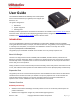
User Guide The USRobotics M2M Cellular Gateway User Guide explains how to install and activate your gateway and configure your device for use. This guide is designed for: Distributors System integrators Field engineers Gateway hardware specifications and technical information are available in the Hardware Guide section of this document. Information about deploying gateway firmware, configuration and software updates is available in the Provisioning Server Guide section of this document.
Secure, redundant firmware and configuration images ensure the unit can revert to previous working settings if a problem is detected Management functions are protected by certificate or password and applied over encrypted links Flexibility Hardware expansion slots allow for additional radio and/or wired interfaces Expansion cards are designed with board-edge connectors for easy installation and replacement in the field Hardware and software development kits are available to partners for develop
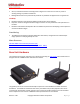
The base unit consists of: Light weight aluminum housing with DIN rail and wall mounting options Two SMA-type antenna interfaces: WWAN Main and WWAN Div/GPS WLAN, GPS, System, and WWAN LEDs showing system status and signal strength 10/100 MB/s RJ-45 Ethernet interface Primary expansion slot pre-loaded with Option serial card - CG1101 9-33 VDC power in with Micro-Fit™, dual row, 4-circuit connector Available secondary expansion slot Internal main board with WWAN module, Ethernet interface
Industrial serial card (CG1102) PoE Ethernet switch (CG1103) Basic Ethernet switch (CG1104) Developer card (CG1105) WLAN Expansion Card - CG2101 Provides 802.11abgn Simultaneous Access Point and Station mode for providing service or connection as a wireless LAN Failover to WLAN client for WAN connectivity Dual SSID Low Cost Serial Card - CG1101 Provides a single RS-232, 921.6Kbaud maximum speed. Industrial Serial Card - CG1102 One RS-232 port with 921.6 Kbaud maximum speed.
USR Universe The USR Universe is the configuration and deployment mechanism for the USR Gateway. From the factory, the base unit is pre-configured for a RS232 serial interface card. On power-up, the gateway connects to the USR Universe over the wired Ethernet port and automatically downloads the appropriate update. If the Ethernet interface is unavailable, then the gateway uses the WWAN interface to download the updates. Tip: You can set the USR Universe to enable or disable the automatic downloads.
While the WWAN network interface is always a direct connection to the Internet, or WAN, the Ethernet interface and optional WLAN interface can act as either a WAN or a local Area Network (LAN). The LAN interface allows local devices to connect to the Internet through the gateway. The network interfaces available on the gateway are: Ethernet interface: can be a WAN or LAN connection depending on the behavior of the WAN/LAN switchover feature at start-up or can be set manually.
Installation Requirements Gateway base unit Included power supply Included WWAN antennas Ethernet cable Web browser on a laptop or smartphone. A service plan from a wireless service provider. o One of the following US wireless service providers: Sprint Verizon Wireless AT&T (requires SIM) T-Mobile (requires SIM) o For non US wireless service providers, any WCDMA based network will work. Browser Requirements For the Provisioning Server: Chrome 27.0 (.1453.110 m) Firefox 21.
For operators using a SIM card, the network settings will populate automatically for most SIM cards. Check the settings of the APN , Username and Password. Update them if appropriate. Click Save changes. Learn more about 3G network settings For CDMA based operators (for Sprint or Verizon, no SIM card is required), click Start programming to start the activation sequence.
To install the SIM: 1. Using a T6 Torx screwdriver, remove the four screws from the top plate on the back panel, and then remove the plate. 2. Insert the SIM into the SIM slot. 3. Replace the top cover plate and screws. Related Topics Selecting a Wireless Operator Activating the Gateway When you activate the gateway, you add the device to the USR Universe. The USR Universe allows you to configure one or more devices with the same firmware, configuration, and developer images.
3. Sign in and complete the Activate Device page. Select or enter a User group, (your personal user group is the same as your username), the type of activation, the serial number, and activation code. 4. Click Activate. Related Topics Creating an Account on the USR Universe Activating the Gateway Using the USR Universe Powering On the Gateway To power on the gateway: 1. Plug the power supply into the power connector on the back of the unit and into a power source. 2. Observe the LEDs on the front panel.
Selecting a Wireless Provider For the minimum, out-of-the-box installation of the base unit, you have to connect the device to a laptop and use the embedded web interface to select the appropriate wireless provider firmware. IMPORTANT: When using the USRobotics USR803510 (GSM/WCDMA only version), selecting the wireless operator is not needed and you can immediately go to step 7 on this page. To connect the gateway to a laptop and select a wireless provider: 1.
Tip: When using an AT&T SIM card, select AT&T. For all other operators using SIM cards, select UMTS generic. 7. Proceed with the wireless provider selection. For Verizon Wireless and Sprint service Make sure the service plan is already associated with the unit (MEID). Scroll down to the CDMA section and click Start programming to complete the activation. Revision: 1.00 Copyright 2015 U.S.
For all SIM card based operators The network settings populate automatically for most SIM cards. Scroll down to the Network Settings section and check the APN, Username, and Password fields. Update if necessary and click Save changes. If the service plan requires a PIN code, scroll down to the PIN Settings section, enable and enter the PIN code, and click Save changes.
4. Slide the card into slot, using the side channels or grooves on the device to guide the card into place. Make sure the screw holes line up. 5. Push gently until the card is flush with the housing. 6. Secure the card with the screws. The following table lists the expansion cards available from Option and the slot.
Related Topics Configuring Expansion Cards Mounting the Gateway The gateway can be mounted on a wall or DIN rail. IMPORTANT: All mounting hardware is installer provided. Mounting on a wall The gateway can be mounted on a wall with six screws. The mounting holes in the base of the gateway have a diameter of 4.3 mm. USRobotics recommends using screws with a minimum width of 4mm and a minimum length of 30 mm (M4x30mm).
Mounting on a DIN rail To mount the gateway on a DIN rail, use two DIN rail adapters. USRobotics suggests adaptors from the following companies: Phoenix Contact DSB Marketing Hammond Configuring the Base Unit When the gateway is connected to a laptop through an Ethernet cable, you can configure the device locally using the embedded web interface. The web interface allows you to configure one device at a time.
Click this tab To do these tasks Home VPN Verifying the Internet Connection Checking the Firmware Version Disabling the WAN/LAN Switchover Feature Managing IP Configuration Settings Configuring the WWAN Interface Choosing a Wireless Operator Setting Up SIM Parameters Setting Up WWAN Connection Parameters Choosing PIN Code Settings Setting up Verizon Wireless or Sprint wireless operators Setting Default Firewall settings Setting Up the DMZ Setting Up Inbound Port Forwarding Setting Up Outbound Port Filte
Logging On to the Base Unit To log on to the embedded web interface: 1. In a web browser, go to the URL: 192.168.1.1. 2. Enter the user name and password, and then click Login. Use the default username admin and password admin. You can change the default username and password later if necessary. Home Tab The Home tab displays the gateway connection status, the connection settings, the different available LAN interfaces and the firmware and software versions installed.
Priority based In priority based mode the gateway will first try to make a WAN connection with the interface on the top row of the table. When the first interface is unable to make a connection to the internet, the gateway will then try the second interface. When the second interface fails the next line will be tried. In order to change the priorities, click on the arrows behind the interface you would like to change. I Revision: 1.00 Copyright 2015 U.S.
IMPORTANT: The gateway decides that it's not connected anymore when: - the Ethernet connection cable is removed. - when a disconnect message of the network is received via the 3G connection - when the WLAN connection is out of range. This functionality can be extended when used together with the connection persistence feature. LAN interfaces Displays a list of the available LAN interfaces and their IP addresses. VPN Tunnels Displays a list of the active VPN tunnels.
Interfaces Tab The interfaces menu groups the settings of all connection technologies Ethernet 3G Connection WLAN Client WLAN Access point Ethernet Tab The Ethernet tab configures the behavior of the Ethernet port on startup and manages IP nework settings. Enabled Enables (Yes) the Ethernet interface on the main board of the gateway or disables (No) the Ethernet interface Revision: 1.00 Copyright 2015 U.S.
Mode This will define the state of the Ethernet interface when the WAN/LAN Switchover feature is disabled. When the WAN/LAN switchover feature is enabled the state of the Ethernet interface will be as in the following table: Result of WAN/LAN switchover feature State of "Mode" End result WAN LAN WAN WAN WAN WAN LAN LAN LAN LAN WAN WAN WAN/LAN Switchover The WAN/LAN switchover feature defines the state of the Ethernet port after the gateway is powered on.
Lease time Lease time is configurable from 2 minutes up to 24854 days. DNS 1 and DNS 2 When the gateway is in LAN mode the DNS fields will be empty by default. As a result the gateway itself will act as a DNS server. All the connected Ethernet devices will receive an DNS address which is equal to the gateway's IP address (by default 192.168.1.1) When the DNS server inside the gateway can't resolve the DNS request it will forward the request to the DNS server of the WAN connection.
3G Connection Tab The 3G Connection tab configures the gateway WWAN interface, as well as 3G and CDMA network settings. It includes the following sections: Connection Status General Network Settings PIN Settings CDMA Connection Status The Connection status section provides information about the wireless network. Operator Name Displays the name of the wireless operator the gateway is connected to. Revision: 1.00 Copyright 2015 U.S.
Signal Strength Displays the received signal strength. ECIO Displays the energy per chip over the interference. This is a typical way to indicate the quality of 3G networks. Technology Displays the technology used by the wireless operator. Voice number Displays the voice number linked to the SIM card for 3G wireless operators. Revision: 1.00 Copyright 2015 U.S.
General The General section configures the WWAN interface on the gateway. Enabled Enables and disables the WWAN (3G) interface, Set to Yes (default) to enable the WWAN interface. If there is no Internet connection available on the Ethernet interface, the device automatically connects to the network using the WWAN interface on startup. Set to No to disable the WWAN interface. The only network connection possible is through the Ethernet interface. Revision: 1.00 Copyright 2015 U.S.
Only upon traffic By default, the device is always connected to the network and can send and receive data in both directions: Internet to gateway, and gateway to Internet. To protect the device from unauthorized access and ensure you only pay for the data you want to send, you can configure the device to connect only when it has data to transmit. Set to Yes to connect the device to the WWAN when it has data to send and disconnect it immediately after.
Allow ICMP Allow ICMP messages to pass the firewall. Most important usage is to allow ping to function on the WAN interface. Limit Wireless Mode Limit wireless mode to a specific technology. This is useful when on the limit of coverage of one technology to avoid ping/ponging between 2G and 3G for example. MTU The MTU packet size: Value range 68 to 1500 Radio firmware selection Selects the wireless operator firmware the device will use on the network.
Network Settings If AT&T or UMTS Generic is the chosen wireless operator firmware, you can configure a number of 3G network settings. APN Sets the APN value automatically based on the SIM card installed. IMPORTANT: When the APN which is set automatically, is not the correct one, you can change it manually. When the APN is manually changed, the gateway will remember this and will use this APN every time it detects this individual SIM card.
o o Automatic: Registers the device to the network corresponding to the SIM card installed. When roaming, the device connects to the roaming partner designated by the wireless operator. Manual: Scans for networks and then lets you select a network different from your home network. PIN Settings When you select AT&T or UMTS Generic as the wireless operator, you may have to enter a PIN code. Enable PIN Enables the PIN code and displays a field for entering the value.
CDMA If Verizon Wireless or Sprint is the chosen wireless operator, click Start programming to provision the gateway. Ethernet Switch When the Ethernet expansion board is inserted into the gateway a new item "Ethernet Switch" will be listed in the interfaces tab. only LAN functionality is available on the Ethernet Switch outputs, no WAN functionality.
IP Config The IP configuration field allows to set: IP address: This is the IP address on which the gateway will be reachable from the Ethernet switches network Default the gateway uses subnet 4 on the Ethernet switch card. Subnet 1 is reserved for the main Ethernet interface, Subnet 2 & 3 for the WLAN SSID1 & SSID2 interfaces. Net mask: Allows to configure a specific netmask, default 255.255.255.
Data counters Data counters will trace the incoming & outgoing traffic of the Ethernet switches outputs since last start. Revision: 1.00 Copyright 2015 U.S.
WLAN Access Point If the WLAN Card is inserted into the gateway it has the ability to be configured as a WLAN access point with a single or dual SSID. This page allows configuring the generic access point settings and the individual SSID settings. Please click here for more information WLAN Client When the WLAN card is inserted in the gateway the WLAN Client tab allows setting up the gateway as a WLAN Client connecting to a pre existing WLAN Network For more information please click here.
Default Policies The Default Policies section sets the basic firewall rules. Default Policies Sets the default firewall rules to accept or reject data flow between the following interfaces: o o o o LAN to WAN LAN to LAN LAN to LOCAL WAN to LOCAL Sets the action for each rule: o o o Accepted: the data is allowed to pass from one interface type to the other interface type.
DMZ The DMZ section configures the demilitarized zone. This feature forwards all incoming data to a specific IP address. Enabled Enables the DMZ. WAN Interface Selects the WAN interface the data will be coming from for forwarding. IP Address Sets the IP address for forwarding all data coming from a WAN interface. Inbound Port Forwarding The Inbound Port Forwarding section forwards data from a WAN interface to a designated IP address and port.
These rules allow you to forward data from a WAN interface to the IP address set in the destination field. The port forwarding rules have a higher priority than the DMZ rule! Click Add to create a forwarding rule. Enter the port information and target IP address in the dialog box and click Save. Outbound Port Filtering The Outbound Port Filtering section defines the data allowed to pass from the Local or LAN interface to the WAN interface. Revision: 1.00 Copyright 2015 U.S.
Outbound Port Filtering Lists the outbound port filtering rules, up to a maximum of 20. By default, all data can be sent to a WAN interface. When an outbound port filtering rule is added, the data sent over the chosen port will be allowed, rejected or dropped. Click Add to create a filtering rule. Enter the port range and select whether to Allow, Reject or Drop the data sent over the chosen port and click Save. Revision: 1.00 Copyright 2015 U.S.
Outbound Trusted IPs The Outbound Trusted IPs section defines IP addresses that can be contacted when LAN-to-WAN traffic is not allowed. Outbound Trusted IPs When the LAN to WAN traffic is rejected or dropped based on the default firewall policies, no data can be transmitted from the LAN to the WAN network. The outbound trusted IP list defines the IP addresses that can be contacted even when LAN-to-WAN traffic is not allowed. Enter an IP address and click Add.
! Inbound Rules WAN -> LAN/LOCAL Next is a list of the PORT FORWARDING rules by priority from high to low: 1. HTTPS (port determined in the >SYSTEM tab) 2. Port forwarding rules 3. DMZ Priority example: If you enable HTTPS and DMZ, you can still use the HTTPS because those port forwardings are processed before the DMZ redirect. ! Outbound Rules LAN -> WAN Outbound rules in order of priority: 1. Port filter rules. (Only used when trusted IP is disabled) 2.
Connection watchdog: This watchdog tests if the active WAN interface is able to connect to the internet. If not it will trigger the next WAN interface in the priority list. When it detects that the 3G interface is not able to contact the internet it will trigger the next WAN interface in the priority list and it will reset or reconnect the WWAN module. You can find here a flow chart of the feature. Timed Reset: resets the gateway after a period of time.
IMPORTANT: The URLs in the table must be the domain name, not the complete URL. For example: www.google.com will be accepted. http://www.google.com will not work. I Use PING in addition to DNS Sends a PING and DNS request to the specified URL/IP addresses Checking interval If no data is received during a time equal to the "checking interval" the connection persistence will start the URL/IP lookup feature.
Set to Monthly and enter the day of the month and the time of the day. Provisioning Tab The Provisioning tab configures how and when the gateway checks for updates from the USR Universe. By default, the gateway base unit connects to the USR Universe each time the device is powered on, and checks for an updated image. The device downloads and installs the update over the WAN interface.
Settings Enable Automatic Provisioning Controls automatic updates from the USR Universe. Set to Yes to automatically check for updates. This happens: o o Each time the unit is powered on. Depending on the "check-in frequency" parameter on the USR Universe. Set to No to disable automatic provisioning. System Tab The System tab configures remote access settings, log file parameters, and manual reset settings.
Time Settings Timezone Sets the timezone used by the unit for the Timed Reset watchdog. NTP server Defines the domain name of an NTP server. Power Savings Turn off LEDs This parameter disables (Yes) or enables (No) the LEDs on the base unit front panel. Revision: 1.00 Copyright 2015 U.S.
Data Counters Reset all data counters This resets all data counters. Related Topics Data Counters Remote Access through HTTPS The Remote Access section configures a port on the gateway for remote access. With remote access, you can log into the embedded web interface from a remote PC or laptop. To set up remote login: 1. Click the 3G connection tab and make a note of the IP address of the WAN connection displayed in IP Configuration. 2. Click the System tab. 3.
Dynamic DNS Enabled Set to Yes to enable Dynamic DNS. Service Provider Selects the dynamic DNS service provider. Host name Defines the host name for the DNS service provider account. User name Defines the user name you have set up with the DNS service provider. Password Defines the password you have set up with the DNS service provider. Use HTTPS Set to Yes to enable HTTPS login. Revision: 1.00 Copyright 2015 U.S.
Status Displays status information. Click Update to refresh the status. Username and Password Username Sets a new username for logging on to the embedded web interface. Password Resets the password. Revision: 1.00 Copyright 2015 U.S.
Logging Customer support may request logfiles to diagnose a problem. To create a logfile: 1. 2. 3. 4. 5. Click Yes to enable logging. Set additional logging parameters according to Customer Support recommendations. Click Save changes. Reproduce the gateway problem. Download the log file by clicking Download log file. Enable logging If set to Yes, the unit logs all gateway activity. Maximum log file size Sets the maximum log file size. USRobotics recommends 256 kB.
Config Export Download config Click to save the device configuration to a file on a laptop. The configuration file can then be uploaded to the Provisioning Server and used for provisioning multiple devices. System Reboot and Factory Reset Two different manual resets are possible on the gateway: system reboot and factory reset. TIP: Automatic resets of the WWAN interface are managed by the connection watchdog feature. Automatic resets of the gateway are managed by the timed reset feature.
NOTE: This is the same as pressing the hardware reset button on the back of the gateway for one second. Factory Reset To reset the gateway to the factory default settings and overwrite all custom configuration changes: 1. Click Factory Reset to restart the device with the original firmware version from the factory. 2. Click Factory reset to confirm. TIP: This is the same as pressing the hardware reset button on the back of the gateway for more than five seconds.
Plugin Tab The Plugin tab configures the serial port settings and the GPS settings. It includes the following sections: Serial Port to TCP local or remote server Serial port settings TCP settings GPS to TCP local or TCP/UDP remote server GPS report settings TCP/UDP selection TCP settings UDP settings Serial Port to TCP local or remote server Enable This parameter enables (Yes) or disables (No) the serial port and presents the serial port settings menu. Revision: 1.
Serial port settings Baud rate This parameter selects the serial port baud rate. Data bits This parameter selects the number of data bits per character. Revision: 1.00 Copyright 2015 U.S.
Stop bits This parameter selects the number of stop bits per character. Parity This parameter selects the type of parity bits per character. Flow control This parameter selects the type of flow control used by the serial port. TCP settings TCP server is Local/Remote This parameter configures the TCP server to Local or Remote. Hostname This parameter defines the hostname of the Remote TCP server. Port This parameter defines the TCP port number.
Enable This parameter enables (Yes) or disables (No) GPS reporting and presents the GPS settings menu. GPS report settings No fix report interval Seconds between reports when no GPS fix is available. Revision: 1.00 Copyright 2015 U.S.
Fix report interval Seconds between reports when GPS fix is available but not moving. Report interval Seconds between reports when GPS fix is available and moving. Moving if moved Number of meters moved between fix or move reports to define as moving. TCP/UDP settings TCP/UDP selection This parameter selects a TCP or UDP session for GPS. TCP settings TCP server is Local/Remote This parameter configures the TCP server to Local or Remote.
UDP settings Hostmname This parameter defines the hostname of the Remote UDP server. Port This parameter defines the UDP port number. Configuring the VPN The VPN tab allows adding and configuring IPSec tunnels. By default the gateway has no IPsec tunnels preconfigured. A tunnel can easily be added by clicking the “+ add IPsec Tunnel” button, a window will prompt the user to enter a name for the new tunnel. Revision: 1.00 Copyright 2015 U.S.
When the tunnel is successfully added a new field in the VPN tab will appear for each tunnel that is added. Tunnels can be removed in the bottom right corner of the field of each tunnel using the “delete tunnel” button. Configuring a Tunnel 3 elements can be configured for each tunnel. Identity IKE Settings IPsec Settings All fields must be configured for the tunnel to become active.
IKE Settings The Internet Key Exchange is a protocol used to set-up the security associations in the IPsec protocol suit. IKE Version: V1,V2 Negotiation Mode (only for IKE V1): Main & Aggressive IKE Encryption: 3DES, AES128, AES 256 IKE Authentication: MD5, SHA1, SHA256 IKE Key Group: DH1, DH2, DH5, DH14 IKE SA Lifetime: must be a value between 60 - 86400 http://en.wikipedia.
Configuring Expansion Cards If the gateway is installed with an Option expansion card, the device automatically detects and identifies the card and displays the appropriate configuration tab in the menu bar.
General Enabled Enables the WLAN access point WLAN Mode Selects a 2.4Ghz or 5GHz access point. Channel Selects the WLAN channel on which the access point has to work. Information: The WLAN channel can only be selected when the WLAN client is disabled. In case the WLAN client is active, the access point will use the channel used by the WLAN client! Enable second SSID Activates a second SSID. Revision: 1.00 Copyright 2015 U.S.
SSID 1 Network name (SSID) Allows you to change the SSID. Broadcast SSID If set to Yes, the SSID will be broadcasted. Encryption Allows you to choose the type of encryption. Password Sets the password. Revision: 1.00 Copyright 2015 U.S.
IP Config IP address Sets the IP address of the WLAN access point. Netmask Sets the netmask of the WLAN access point. Enable DHCP server Enables the DHCP server. DHCP range Sets the DHCP range for the DHCP server. Revision: 1.00 Copyright 2015 U.S.
DNS 1 and DNS 2 When the gateway is in LAN mode the DNS fields will be empty by default. As a result the gateway itself will act as a DNS server. All the connected Ethernet devices will receive an DNS address which is equal to the gateway's IP address (by default 192.168.1.1) When the DNS server inside the gateway can't resolve the DNS request it will forward the request to the DNS server of the WAN connection.
General Enabled Click Yes to enable the WLAN client, and then click Save changes. IP Config IP Mode Click Dynamic to use IP addresses provided by the DHCP server Click Static to use a fixed IP address. Enter the IP address, netmask and DNS information. Revision: 1.00 Copyright 2015 U.S.
IP Config Displays the IP, netmask and gateway addresses of the connected WLAN network. Available & Known networks Lists the WLAN networks within range and displays the signal quality, SSID, status, and encryption method of each. Click the Refresh icon to refresh the network list. Connecting to a WLAN Network To connect to a WLAN network: 1. Click the network name. 2. Enter the network password and click Connect. 3. Note the status change to connected in the Available & Known Networks list.
1. Click Manual connection. 2. Enter the network SSID, select an encryption type and enter the network password. 3. Click Save. Disconnecting from a WLAN Network 1. Click the Wi-Fi network to disconnect. 2. Click Forget network. Revision: 1.00 Copyright 2015 U.S.
Hardware Guide The Hardware Guide provides the detailed technical information and hardware specifications for the gateway base unit. This guide is designed for: Third-party developers Distributors System integrators Field engineers Details about installing and configuring the gateway are available in the User Guide section of this document. Information about deploying gateway firmware, configuration and software updates is available in the Provisioning Server Guide section of this document.
IP-65 requirement Below you can find the parts for the encasing which are needed to fulfill the requirements for IP-65. All these parts can be ordered by TAKACHI: 1x box BACK 203013G or BCPK 203013S, 1x plate BMP 2030P, 1 x screws (20pcs) MT4-8T, 1x bracket (2x4 pcs) BLF-2G(PC-GF) or CK-26P (metal SS) 3x cable gland MG-12S (3 inputs) Revision: 1.00 Copyright 2015 U.S.
Front and Back Panels The front and back of the gateway case consist of a top panel and a bottom panel secured with Torx T6 screws. The top panels cannot be changed. The bottom panels can be customized based on the requirements of the expansion card. Revision: 1.00 Copyright 2015 U.S.
Front Panel 3 1 2 4 Connectors 1 2 3 4 WWAN Diversity antenna connector SMA-female Ethernet port 10/100 Mbps RJ-45 WWAN Main antenna connector SMA-female Torx T6 screws LEDs LED Descriptions Bottom Front Panel The bottom front panel covers the front expansion slot and is removed when installing an expansion card.
Back Panel Connectors 1 1 Power connector 2 2 9-33 VDC Micro-Fit 3.0, dual row, 4 circuits Reset button Press and hold for less than five seconds to reset the unit to the last working settings. Press and hold for five seconds or more to reset the unit to factory settings Bottom Back Panel The bottom back panel covers the opening for the back expansion slot and is removed when installing an expansion card.
LED Descriptions LED Description WLAN State Indicates the connection status of the WLAN interface Off: not installed Orange: Wlan board = OK, client not connected and AP not enabled Orange blinking: AP disabled and Client connected / data traffic Red: board error/ (Any that causes AP or Client not to work) Green: AP enabled Green flashing: AP enabled and Client connected/data traffic Indicates the signal strength of the WLAN interface Off: off or not connected Orange: moderate signal strength Red: bad si
Main Board Specifications The gateway is designed with one main board and two additional expansion boards. Main Board The main board is identical for each base unit and is designed around a micro-controller which controls a WWAN module and the Ethernet interface. Main Board Block Diagram (PDF) --> http://support.usr.com/support/3510/files/m2m_box_im_0_0.pdf Internal Power Supply Stable 3.4V power rail Reverse polarity protection Over-voltage protection up to 60V Current limiter at 1.
24 MHz clock signal Master reset signal High speed USB interface SDIO interface GPIO signals Expansion Card Specifications Wi-Fi Card Low Cost Serial Card Industrial Serial Card Basic Ethernet Switch PoE Ethernet Switch Developer Card Telematics Card WLAN Card Specifications CG2101 Specifications: According to 802.
Note: 5GHz WLAN operation In order to reduce the potential for harmful interference to co-channel mobile satellite systems, the operation in the 5150-5250MHz band (channels 36 to 48) is restricted to indoor usage only. Note: group re-keying The WLAN client of the gateway connected to a WLAN access point configured with WPA and group re-keying disabled is currently not supported. RF EXPOSURE WARNING A minimum distance of 20cm must be maintained between the user's body and the device antenna.
Low Cost Serial Card Specifications Specifications: Female DB9 connector One serial port RS-232, 921.6 Kbaud maximum speed Note: The serial card is DCE device! Connect the Gateway with a DTE device (laptop) In order to connect the gateway to a laptop or any other DTE device you should use a regular straight cable. Revision: 1.00 Copyright 2015 U.S.
Gateway (DCE) Connect the Gateway with another DCE device (modem, PLC,...) In order to connect the gateway to another DCE device you should use a cross cable. (= null modem cable). Industrial Serial Card Specifications Specifications: RS232 One RS-232 serial port, 921.6 Kbaud maximum speed The RS232 interface on the industrial serial card is identical to the one on the low cost serial card. Please have a look at this low cost serial card for more info on the RS232 interface. Revision: 1.
RS485 One 22 KV isolated RS-485 serial port, 921.
Note: By default the TX and RX of the RS485 connection are disabled. So you have to enable them before you can start using the RS485 port. (You can enable this by using the DE and RE signals). For a 2 wire interface (=half duplex) you should of course only enable one direction at the same time. Below an example of how to do this in your code. (The example shows how to activate both DE and RE) #include #include #include # include #include
Basic Ethernet Switch Specifications Specifications RJ-45 receptacle tab on top 4-port 10/100 Base-T One uSD card connector available Auto-MDIX Pinout Yellow LED: Active when operating speed is 100Mbps Inactive when operating speed is 10 Mbps or when not connected Green LED: Active when valid link is detected Blinks when activity is detected Inactive when not connected Revision: 1.00 Copyright 2015 U.S.
IMPORTANT: The auto-MDIX feature is always activated on the gateway. This feature automatically detects the required cable connection type (straight or crossed), and configures the connection appropriately, removing the need for crossover cables. In order for auto-MDIX to work correctly, auto-negotiation (auto speed and auto duplex) must be enabled on both sides of the link. Note that auto negotiation is always active on the gateway.
Pinout Yellow LED: PoE indicator Green LED: Active when valid links is detected Blinks when activity is detected Inactive when not connected IMPORTANT: The auto-MDIX feature is always activated on the gateway. This feature automatically detects the required cable connection type (straight or crossed), and configures the connection appropriately, removing the need for crossover cables.
Power Supply Connector: Examples of the connector you should use are: o o Phoenix (MC 1,5/2ST-3,81) Würth (691361300002) Operating voltage: 50 - 57Vdc, typical 56Vdc Power consumption: The mainboard of the gateway consumes about 10W, the Ethernet board can consume up to 60W (4x15w or 2 x 30W. So the total power should not exceed 70W. The POE Ethernet board has an internal one time fuse of 2A The power plug is delivered together with the PoE Ethernet Switch expansion card.
SAFETY WARNING When using the PoE board at a power level lower or equal to 30W the temperature range in which you can use this board is equal to the temperature range of the gateway itself (30°C to +70°C). However when the PoE board operates at a power level between 30W and 60W the temperature range is limited to -30°C to +45°C. When using an AC adapter make sure that the ambient temperature doesn’t exceed the specified temperature limits of the AC adapter.
CDMA bands: BC0,1 Output Power Power Class 4 (2W, 33dBm) for GSM, GPRS 850/900 MHz bands Power Class 1 (1W, 30dBm) for GSM, GPRS 1800/1900 MHz bands Power Class E2 (0.5W, 27dBm) for Edge 850/900MHz bands Power Class E2 (0.4W, 26dBm) for Edge 1800/1900 MHz bands Power Class 3 (0.25W, 24dBm) for UMTS 850/900/1900/2100 MHz bands Antenna Interfaces Main WWAN Antenna The main antenna is labelled WWAN Main on the front panel. Learn about antenna recommendations.
RF EXPOSURE WARNING To comply with FCC and Industry Canada regulations limiting both maximum RF output and human exposure to RF radiation, maximum antenna gain must not exceed: Cellular (800MHz) band < 4 dBi PCS (1900MHz) band < 3.5 dBi AWS (1700MHz) band < 3.5 dBi To comply with the CE regulations, maximum antenna gain must not exceed the antenna gain of the Taoglas TG.09.0113 antenna. Diversity WWAN Antenna The diversity antenna is labelled WWAN Div GPS on the front panel.
Maximum VSWR < 2.5:1 with 50 ohm reference impedance Polarization RHCP antenna or a vertical polarized antenna Frequency range Frequency range for GPS: 1575.42MHz ± 1MHz Efficiency Efficiency: > 50%. WLAN interface The WLAN antenna is labelled WLAN Main on the bottom back panel. Learn about antenna recommendations.
RF EXPOSURE WARNING To comply with CE, FCC and IC regulations limiting both maximum RF output and human exposure to RF radiation, maximum antenna gain must not exceed 3 dBi. Antenna Recommendations A number of good antennas are available on the market for use with the gateway. Below is a list of antennas which can be used as a reference for each functionality. All antennas listed below are made by Taoglas and are available via DigiKey Main WWAN Antenna Taoglas TG.09.
Option B Taoglas TG.10.0113 Not recommended for the main antenna (marginal low band performance) Recommended for high band diversity antenna Acceptable as low band (700-800-850-900MHz) Diversity antenna Recommended for GPS antenna WLAN Antenna Taoglas GW.59.3153 Recommended for both 2.4 Ghz and 5 Ghz bands Related Topics RF Specifications 3G Connection Tab Ethernet Specifications Ethernet Interface RJ-45 receptacle tab on top 10/100 Mbps 100BASE-TX Auto-MDIX Revision: 1.
Pinout Yellow LED: Active when operating speed is 100Mbps Inactive when operating speed is 10 Mbps or when not connected Green LED: Active when valid links are detected Blinks when activity is detected Inactive when not connected IMPORTANT: The auto-MDIX feature is always activated on the gateway. This feature automatically detects the required cable connection type (straight or crossed), and configures the connection appropriately, removing the need for crossover cables.
WAN/LAN Switchover Feature The WAN/LAN switchover feature defines the state of the Ethernet port at power-on. By default, this feature is enabled. Learn how to disable WAN/LAN Switchover. Two modes are possible: WAN mode: the Ethernet interface act as a WAN interface LAN mode: the Ethernet interface acts as a LAN interface Each time the unit is powered on: Gateway sends a DHCP discover message over the Ethernet interface.
WAN/LAN Switchover Flow Diagram Related Topics Ethernet Tab Revision: 1.00 Copyright 2015 U.S.
Environmental Specifications Operating temperature: -30°C to 70°C Storage temperature: -40°C to 85°C Humidity operational: 5% - 95% non condensing Power Requirements Base Unit Power Supply Input voltage must be between 9V - 33V DC Internal electronic fuse limits the input current to 1.2A USRobotics recommends to use a wire between the gateway and the external power supply of 22 AWG! SAFETY WARNING This device operates on DC power provided via a DC power supply or AC power adapters.
Power Connector The power connector is a Micro-Fit connector from Molex (MX-43025-0400). Power Connector Drawing (PDF) --> http://support.usr.com/support/3510/files/molex_43025400_drawing.pdf Power Connector Datasheet (PDF) --> http://support.usr.com/support/3510/files/molex_43025400_datasheet.pdf Pinout Internal Power Circuits The voltage applied by the power adapter to the gateway is converted into different voltage levels by the main board.
o o V_PWR: Is the voltage level of the power adapter limited to 1.2A. A little voltage drop lower than 1V will be caused by the protection circuit. 3V4: A 3.4V power rail made by a dedicated power circuit which is used on the main board but also accessible by the expansion boards Low power circuit generated by the micro controller Provides three voltage rails for very limited power: o o o 3V3: A 3.
Internal Power Circuits Block Diagram SIM Card Requirements The gateway has an integrated (U)SIM interface compatible with the ISO7816 IC card standard. The 3GPP standard defines three operational voltages for the supply voltage of the SIM card: 1.8V, 3V and 5V. The gateway supports two voltages: 1.8V and 3V. The 5V-only SIM cards are rarely used and are not supported by the gateway. General requirements: Changing of SIM cards while in operating mode, or hot-swapping, is not supported.
Certification and Operator Approvals For detailed info about the obtained regulatory certification and operator approvals, please select your gateway product: USR3510 3G Americas USR803510 3G EMEA Safety warnings Please read the following guidelines carefully. Not following these guidelines can cause harm to the gateway, yourself or other persons. RF EXPOSURE WARNING A minimum distance of 20cm must be maintained between the user's body and the device antennas.
Explosive atmosphere Turn off your device in any area with a potentially explosive atmosphere. It is rare, but your device could generate sparks, which could cause an explosion or fire. Areas with a potentially explosive atmosphere are not always clearly marked. They include fueling areas (petrol filling stations), below deck on boats, fuel or chemical transfer or storage facilities and areas where the air contains chemicals or particles, such as grain, dust, or metal powders.
manufacturer reserves the right to make changes to the content of this document and/or the products associated with it at any time without obligation to notify any person or organization of such changes. In no event will the manufacturer be liable for direct, indirect, special, incidental, or consequential damages arising out of the use or inability to use this product or documentation, even if advised of the possibility of such damages. For questions regarding your product or declaration, contact: U.S.
Operator approvals The USR3510 3G Americas is approved by the following network operators: Aeris AT&T Bell Mobility Sprint T-Mobile Telus Verizon Wireless Regulatory information This device complies with Part 15 of the FCC rules and with Industry Canada license-exempt RSS standards.
model CG1102, the Industrial serial card; model CG1103, the Ethernet switch with PoE; model CG1104, the Ethernet switch; model CG1106, the Telematics base board; model CG2101, the WLAN expansion card; model CG3101, the Telematics I/O expander. The R&TTE declaration of conformity can be downloaded at the bottom of this page. E-mark The USR803510 3G EMEA is complying with the Automotive EMC requirements according to regulation UN ECE-R10 revision 4 and EU Automotive EMC directive 2004/104/EC.
The amount of testing and certification work highly depends on the supported functionality. Digital devices containing no wireless transmitter can still transmit unwanted emissions (unintentional radiators) which can interference with other devices. Devices containing a wireless transmitter should make sure their RF behavior is within specification and meets safe limits for people. The most common regulatory approvals are described now.
Please visit the FCC website for more detailed info on the equipment authorization procedures and the different FCC rule parts. These FCC tests can be executed in authorized test labs. Industry Canada (IC) When you want to sell/use your expansion card in both Canada and USA, it is advised to do the IC and FCC testing together. Typically the same testing can be performed, resulting in reduced testing costs.
REACH regulation; When developing a new expansion card one should make sure the full device is still compliant. For the R&TTE directive, this means evaluating the product according to the applicable standards related to EMC emissions, EMC immunity (ESD, surge,...), radio spectrum, RF exposure and product safety. Some typical standards include: EN 301489 and/or EN 55022/55024 for EMC emissions and immunity (ESD,…); EN 60950-1 for ITE safety; EN 300 328 for 2.
USR Universe Guide The USR Universe Guide explains how to deploy firmware, configuration, and developer images to multiple devices. This guide is designed for: Distributors System integrators Developers Field engineers Information about installing and configuring the Gateway is available in the User Guide section of this document. Details about Gateway hardware specifications and technical information are available in the Hardware Guide section of this document.
1. Visit the page: http://www.usr.com/activate/3510 and click the ‘Green’ button…Sign up now! 2. Enter the required fields and click Sign up > Revision: 1.00 Copyright 2015 U.S.
3. If everything is accepted by the validation, a confirmation box will appear that an email has been sent and you need to open your email account to validate your email address. 4. Click the email link and your browser will open and direct you to USR Universe. 5. You are now signed in and can start to use USR Universe! Signing In To Sign in to USR Universe: 1. In a web browser, enter the URL: http://www.usr.com/activate/3510. 2. Enter your email and password and click the 'Blue' button...
Activating a Gateway Using USR Universe Before being able to activate a device, you need to have already created a group (including correct device type). You can activate a Gateway two ways: 1. Activate a single device 2. Activate devices in bulk Activation of a single device From the ‘Device’ section please click the ‘Activate new device’. Then fill in the Serial and activation code for this device and choose which group it should belong to (mandatory).
Activation of devices in bulk It is only possible to use the Bulk Device activation when all the devices being activated are the exact same device type and being added to the same group. From the ‘Device’ section please click the ‘Activate new device’. Then click the tab ‘Bulk Device Activation’ Then fill in the Serial and activation code (separated with a comma) for the devices to be activated - 1 device per line.
Groups The main purpose of a group is that a user can provision (Over-the-Air) the exact same settings/software to a number of devices, while the devices are out in the field. A Gateway device must always be inside a group, but can ONLY belong to 1 group A Gateway hardware device is owned by the group (and not a person) Only the same device type can be inside 1 group. Add a group To add a new group, click the 'Add Group' button within the Device section.
The user can then start to edit the group, adding devices, invite owners and members Adding device(s) to a group There are 3 possible ways to add a device or devices to a group: 1. Activate a single device 2. Activate devices in bulk 3. Move from another group Adding a single device From the ‘Device’ section please click the ‘Activate new device’. Then fill in the Serial and activation code for this device and choose which group it should belong to (mandatory).
Adding devices in bulk It is only possible to use the Bulk Device activation when all the devices being activated are the exact same device type and being added to the same group. From the ‘Device’ section please click the ‘Activate new device’. Then click the tab ‘Bulk Device Activation’ Then fill in the Serial and activation code (separated with a comma) for the devices to be activated - 1 device per line.
Moving a device from another group Go to 'Devices/Group/Manage devices', then check the device(s) you want to move and click 'Change group' Then choose the destination group and confirm the changes.
To change the group name and description: 1. Click Devices in the menu. 2. Select the group you want to edit. 3. In the group overview, select 'Edit group'. 4. Enter your changes and click 'Update' Note: This action can also done per device using the device detail page Revision: 1.00 Copyright 2015 U.S.
Setting the Check-in Frequency The check-in frequency is the interval at which a device connects to the USR Universe and checks for updates. To set the check-in frequency: 1. Click Devices in the menu. 2. Select the group you want the change the check-in frequency. 3. In the group overview, select 'Edit group'. 4. Choose the desired Check-in frequency and click 'Update'. Revision: 1.00 Copyright 2015 U.S.
IMPORTANT USRobotics recommends caution when setting the check-in frequency to NEVER. If NEVER is selected, the next time the device connects to the USR Universe, the automatic check-in function will be turned off permanently. Even if the check-in frequency is changed later, the device will not connect with the USR Universe and download the new setting. All the devices in this group will be updated with the new check-in frequency next time the devices check-in.
2. In the 'Software section' you will see the current software set for this group. To change the group software settings, click the 'Manage software' button. Note: This action can also be done per device using the device detail page. Edit Group Software To edit the software assigned to a group: Revision: 1.00 Copyright 2015 U.S.
1. Go to 'Devices' and choose the desired group Revision: 1.00 Copyright 2015 U.S.
2. Within the group page, choose 'Manage software'. Revision: 1.00 Copyright 2015 U.S.
Then you see all the software that is currently set for this group. For example, to change the application click 'Choose a different application'. Now you can choose any of the applications that are made available for this group. Devices The main function of the USR Universe is to provide an easy-to-use mechanism for updating Gateway devices before and after deployment in the field.
Set the check in, or update frequency, which defines when a device checks the USR Universe for available updates Select specific software for automatic download when the device connects with the USR Universe Ignore updates if you don't want automatic downloads to occur Manage and Sorting Devices The group device list is an inventory of all Gateway base units in that group for which the user has provisioning access. Revision: 1.00 Copyright 2015 U.S.
To see the group device list: 1. Click Devices in the menu. 2. Select a group. 3. Then click on the 'Manage Devices' button. Revision: 1.00 Copyright 2015 U.S.
4. Then you see an overview over all the devices that belong to this group. Sorting the Device List When there are too many devices to view on one screen, click the header to sort based on 'Name', 'Serial number' and 'Last Check-in', ascending or descending.
To set the check-in frequency for a specific device: 1. Click Devices in the menu. 2. Select the group where the device is located. 3. Then click on the 'Manage Devices' button. Revision: 1.00 Copyright 2015 U.S.
4. Then you see an overview over all the devices that belong to this group. Click on the name of the device you want to change the check-in frequency. You can also change check-in frequency for multiple devices at the same time by clicking the checkboxes and then the 'Change check-in frequency button at the bottom of the page. 5. In the Device overview, click the 'Edit device' button. Revision: 1.00 Copyright 2015 U.S.
6. Choose the desired Check-in frequency and click 'Update'. IMPORTANT: USRobotics recommends caution when setting the check-in frequency to NEVER. If NEVER is selected, the next time the device connects to the USR Universe, the automatic check-in function will be turned off permanently. Even if the check-in frequency is changed later, the device will not connect with the USR Universe and download the new setting.
To enable automatic update and select the software for download at the next device check-in: 1. 2. 3. 4. Click Devices in the menu. Select the group. Click Manage devices and choose your device Ensure Ignore updates is NOT selected for each software type you want to enable automatic update. If ignore updates is selected, please deselect and click 'Apply changes'. Note: This action can also be done per device using the device detail page.
To ignore automatic update: 1. 2. 3. 4. Click Devices in the menu. Select the group. Click Manage devices and choose your device. Select Ignore updates for each software type you want to disable automatic update. Select 'Ignore updates and click 'Apply changes'. Note: This action can also done per device using the device detail page.
To change the device name and description: 1. Click Devices in the menu. 2. Select the group where the device is located. 3. Then click on the 'Manage Devices' button. Revision: 1.00 Copyright 2015 U.S.
4. Then you see an overview of all the devices that belong to this group. Click on the name of the device you want to change the name and description. 5. In the Device overview, click the 'Edit device' button. Revision: 1.00 Copyright 2015 U.S.
Choose the desired name and description and click 'Update'. Deactivating Devices If you need to disassociate a device from the USR Universe for some reason, for example the device is damaged, or will be provisioned through a different account, you can deactivate the device. NOTE: Deactivation means that you will no longer have access to the device through the USR Universe. Revision: 1.00 Copyright 2015 U.S.
To deactivate a device: 1. 2. 3. 4.
The following items can differ: Check-in frequency Firmware Radio Firmware Config Application If a device has a custom setting it is shown with the text 'Custom' next to the device name in the device overview. Custom If you want to see which settings are custom (or make changes), click on the device name to go to the device detail page. Reset a custom device to the group settings You can at any time change the settings back to its group settings.
Users All Gateway devices need to be associated with a group and it is the groups users who can manage and provision software to devices in that specific group. A group can have users with 2 different roles, with different permissions: 1. Owner 2. Member An owner of a group can at any given time invite other users to their group or remove a user. User Roles Within a group there are 2 different kind of roles; Owner and Member.
Add a new user It is always possible to add new owners/members to a group. ONLY owners of a group can add new users to a group. In order to add a new user, the following steps need to be followed: 1. Within the Group, go to user section and click ‘Manage users’ 2. Click ‘Add user’ the fill in the email address to the person you want to invite, and select the role (owner/member) Revision: 1.00 Copyright 2015 U.S.
3. When you click ‘Invite’ the person who is invited will then receive an email invite, and will become owner/member of this group when confirmed. Change roles in a group It is possible to change the role to a person inside a group from a member to an owner and vice versa. Only owners of a group are able to change roles of people within the group. There must always be at minimum 1 owner within a group, however there can be more than 1 owner.
2. Click the ‘Checkbox’ to the user(s) that should be removed 3. Then click ‘Remove from Group’ 4. Then a confirmation box appears showing that the chosen user(s) has been removed from the group. Managing Software The USR Universe allows you to manage the firmware and software images for the Gateway base unit. Each image can have multiple releases.
Managing System Firmware The USR Universe allows you to see a list of all System firmware releases. Note: Releases of Firmware are uploaded by USRobotics. You cannot upload or download versions of the firmware from the USR Universe. The list of System firmware is displayed by clicking Library in the menu. Then click the 'Firmware' button. Revision: 1.00 Copyright 2015 U.S.
You will then see an overview of all the available 'Firmware' Managing Radio Firmware Radio firmware is firmware for the radio module in the USR3510 devices. Note: Releases of Radio firmware are uploaded by USRobotics. You cannot upload or download versions of the radio firmware from the USR Universe. Revision: 1.00 Copyright 2015 U.S.
Radio firmware is displayed by clicking the 'Library' on the menu: Then click the 'Radio Firmware' button: Revision: 1.00 Copyright 2015 U.S.
Then you will see an overview of all the available 'Radio Firmware' Managing Applications & Configs Note: The below example is referring to applications. If you want to manage configurations instead, please follow the same steps, but click the 'Configurations' button. Once an SDK application has been built, debugged & tested, you can deploy this application to a host of devices. This is where the USR Universe comes in.
Clicking on ‘View Applications’ will get you to the section where you can upload your application to the USR Universe. Revision: 1.00 Copyright 2015 U.S.
In order to upload a new application, please click the '+ Add new application' button. For example, assume you created an application called SensorMaster. Here you enter the name of the application, add the application file and you can add an icon, description and what's new. Then click on 'Upload' to create a new application. Revision: 1.00 Copyright 2015 U.S.
After the application is uploaded and created, you will see your application in the application overview. But as you can see, this application is not yet made available for any groups. So go ahead and click 'View details'. Select the version(s) you want to become available and to which groups. (In the above example, V1.0 is chosen to become available for the group '2nd Floor') Revision: 1.00 Copyright 2015 U.S.
Now this application will be available for the '2nd Floor' group. Select this application for the group in order to take effect. Go to 'Devices' and choose the desired group (i.e. 2nd Floor) 2nd Floor Within the '2nd Floor' group, choose 'Manage software'. Revision: 1.00 Copyright 2015 U.S.
Then you will see all the software that is currently set for this group. We now want to change the application for this group. Go ahead and click 'Choose another application' Now you can choose any of the applications that are made available for this group. In this example it is the SensorMaster application.
(You can also change application per device, following the same procedure as mentioned above for the group settings, but choosing a specific device instead of group level) Editing Your Account Once you have created an account, you can change your user profile, including: First name Last name Company name Email address Password To edit: 1. Click the 'Account' in the menu and select Edit Profile. Edit the fields as required. Revision: 1.00 Copyright 2015 U.S.
2. If changing the password, enter the current password. 3. Click Update profile. Revision: 1.00 Copyright 2015 U.S.
Troubleshooting How does connection priority work in conjunction with connection persistence? What is the priority order between port forwarding rules, DMZ and remote login in the internal routing table? How does the automatic upgrade feature work on the USR Universe? Why does the page display incorrectly? How does connection priority work in conjunction with connection persistence? First of all it is crucial to understand both features run as separate services on the Gateway although their output is heavi
Example: Connection priority is configured in following order: 1. WLAN; 2. Ethernet; 3. 3G interface. The WLAN interface reports it is connected although connection persistence reports it cannot resolve the requested destination address. (e.g. Gateway is connected to a WLAN network with a captive portal active). Gateway will start the Ethernet interface. When Ethernet is connected and connection persistence reports the link is accepted the gateway will start using the Ethernet interface.
Reject everything DMZ The DMZ has a lower priority than the remote login and port forwarding rules, so activating the DMZ results in the next routing table: Port 1800 is open for HTTPS Send all incoming data to the address specified in the DMZ Port 443 is open for HTTPS Reject everything Port Forwarding Rules Adding port forwarding rules results in the next routing table: Port 1800 is open for HTTPS IP forwarding rule 1 IP forwarding rule 2+ Send all incoming data to the address s
Automatic Update Flow Chart Why Does the Page Display Incorrectly? If the USR Universe or Gateway embedded web interface does not display correctly, reports error messages, or does not display at all, make sure that your PC meets the following minimum browser requirements: For the USR universe: Chrome 27.0 (.1453.110 m) Firefox 21.0 Internet Explorer 9 (.0.8112.16421) Internet Explorer 10 (.0.9200.16540) For the Gateway one-device web interface: Internet Explorer 9 Safari 5.
Chrome (Windows 27.0.1453.110, Mac 26.0.1410.65) Opera (Windows 12.02, Mac 12.10) Revision: 1.00 Copyright 2015 U.S.
Licenses Most of the source code used in the Gateway is available under free, open source license. The following licenses are used: GPLv2 - http://support.usr.com/support/3510/licenses/GPLv2.htm GPLv3 - http://support.usr.com/support/3510/licenses/GPLv3.htm LGPLv2 - http://support.usr.com/support/3510/licenses/LGPLv2.htm LGPLv2.1 - http://support.usr.com/support/3510/licenses/LGPLv21.htm DROPBEAR - http://support.usr.com/support/3510/licenses/dropbear.htm GOBISERIAL - http://support.