
Installation guide

2
rev 0.0 2/13© 2013 U.S. Robotics Corporation
Network Connection:
MPORTANT: Do not exceed 90 meter maximum length between any network to network end-points or
network to monitor end-points.
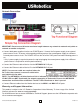
● Connect both power supplies into the rear POWER ports*. Connect the first power supply to an external
power source circuit. To assure uninterrupted monitoring connect the second power supply to a different
external power source circuit. The POWER LEDs to the left of the RJ45 ports illuminate indicating power is
on.
* Only 1 power supply is required to power the tap but plugging the second power supply into a different
power source is required for uninterrupted monitoring.
● Connect the Ethernet cable of device A to the NETWORK A RJ45 port.
● Connect the Ethernet cable of device B to the NETWORK B RJ45 port.
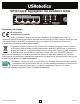
NOTE: If a crossover cable was required before for
Rx/Tx link, then connect a crossover cable to the
port indicated in the table.
NOTE: The NETWORK is bi-directional and link is indicated by simultaneous illuminated LINK LEDs.
If LINK LEDs are NOT illuminated, the network connection is backwards. Reverse the NETWORK
connections and link will be established. The ACT LEDs illluminate as data is passed.
● Connect Ethernet cables from the Monitor devices to the MON 1 and MON 2 RJ45 ports.
Warranty and Support Information:
This product is subject to the U.S. Robotics Corporation Limited Warranty. To view a copy of the Limited
Warranty, please see:
www.usr.com/support/4505
For information on how to contact USRobotics Technical Support, please see the USRobotics corporate web
site at:
www.usr.com/support