USR4204 User Guide Console Server & Power Switch USR4204 User Guide R24.0792.00 Rev 1.
USR4204 User Guide Contents Contents ............................................................................................................. 2 Symbols Used In This User Guide ........................................................................... 4 Important Safety Instructions ................................................................................ 5 Introduction ........................................................................................................
USR4204 User Guide Flashing firmware ........................................................................................... 36 Clearing A Forgotten or Disabled Administrator Name and Password ...................... 36 Suggested Security Guidelines .......................................................................... 37 What are "displayable characters"? ................................................................... 37 What are programmable characters? .........................................
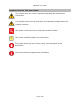
USR4204 User Guide Symbols Used In This User Guide This symbol alerts the user to important operating and maintenance instructions. This symbol warns the user that there are hazardous voltages within the product enclosure. This symbol invites the user to read more technical details. This symbol identifies helpful user information. This symbol warns the user to stop, read, and understand critical information. This symbol denotes supplemental information.
USR4204 User Guide Important Safety Instructions SAVE THESE INSTRUCTIONS This manual contains instructions and warnings that should be followed during the installation, operation, and storage of this product. Failure to heed these instructions and warnings may affect the product warranty. WARNING: Hazardous Voltage! To reduce the risk of personal injury from electric shock, do not remove the cover. There are no field-serviceable or user-serviceable components inside.
USR4204 User Guide Introduction Overview of Main Features Out-of-Band Remote Management Out-of-band remote management uses a secondary communications channel, typically a pair of dial-up modems, to connect to the management ports of remote equipment and to control outlets that supply power to the remote equipment. With one USR4204 a single channel can control up to four management ports and two power ports. The USR4204 allows a remote manager to select and control ports via a simple menu-driven interface.
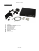
USR4204 User Guide Package Contents 1 1 1 1 1 2 6 4 1 USR4204 VersaPower Kit – Universal Power Supply 6-foot RJ45 rollover cable RJ45-to-DB25M adaptor RJ45-to-DB9F adaptor Rackmount brackets Bracket mounting screws Rubber feet Reference Guide Page 7 of 52
USR4204 User Guide Physical Features 1. Terminal Port - RS-232 port for connection to modem or computer serial port to configure and manage the USR4204 and connected devices. The terminal port supports an RS-232 asynchronous serial DTE connection via an RJ45 jack. See appendix A for pinout details. Terminal port activity can be monitored using the two adjacent LEDs. Both LEDs light when the terminal or modem connected to this port signals that it’s ready to receive or transmit data.
USR4204 User Guide The external power supply input delivers operating power to the USR4204 from the external low voltage power supply that is included with the product.
USR4204 User Guide Getting Started – Local Access This section describes how to verify the unit is operational. Once installed, this is also the setup process for local access. For detailed unit configuration and advanced operating features see Physical Installation, Remote Access, or Product Operation.
USR4204 User Guide Physical Installation Standalone To use the USR4204 on a flat, horizontal surface, affix the four adhesive rubber feet to the bottom of the housing in the four corners. Rack Mounting To mount the USR4204 in a 19" rack, securely fasten the two rackmount brackets to the sides of the USR4204 using the supplied hardware and mount the USR4204 in a 1U space in a 19" rack.
USR4204 User Guide Connecting Network Devices Connecting to Network Device Console Ports When connecting network device console ports the type of device will determine the type of cable required. Console Port RJ45 DTE RJ45 DCE Cable Straight Ethernet Cable Rollover Cable Additional adapters may be required when connecting to console ports that use DB9 or DB25 connectors. Connecting To Power Ports Mains Input Port The mains power input port is the source of power to both of the USR4204 power out ports.
USR4204 User Guide Remote Access Setting Up Confirm requirements: Computer terminal with a COM port Terminal emulation application Modem at the management site Modem at the equipment site Access to phone line (analog connection only) or Cellular service (cellular connection only) at both locations To remotely connect to the USR4204, the modem must be configured before connecting it to the USR4204 at the equipment site.
USR4204 User Guide The attached equipment is now ready to be remotely managed. Remotely connecting and managing using dialup To connect to the USR4204 and manage the attached devices at the equipment site, the user will need a terminal emulation application, a connected modem, and a phone line at the management site. From the terminal, dial the phone number of the modem at the equipment site. Once the modems connect, the USR4204 will send the Main Menu or login prompt to the management terminal.
USR4204 User Guide Product Operation User interface The USR4204 user interface is organized into menus. See Figure 1 for a map of all menus. Each menu contains commands, text, and status where appropriate. Commands listed on the following pages are shown within single quotes ('), programmable names are shown within double quotes ("). Commands are single characters that either perform an action or provide navigation to another menu. Commands are not case-sensitive.
USR4204 User Guide Figure 1 Login Screen (If security is enabled) Main Menu Arm Ctrl-B for Break Menu (W) Configure Parameters Menu (Y) Configure Security Menu (U) Configure Port Menu (Z) Port Menus Admin Password Menu (0) User Menus Note: Menus with red borders are not available to users if security is enabled Page 16 of 52
USR4204 User Guide Command Reference Command Connect to Port Toggle Power Port On or Off Arm Ctrl-B for Break Configure Port Parameters Rename Power Port Rename Console Port Copy Baud Rate and Parity to all Console Ports Change Console bps rate Change Console parity Configure Parameters Change Inactivity Timeout Customize USR4204 Name Change Char for Escape Change Char for Menu Change Char for Xon Change Char for Xoff Toggle Cellular Mode Enter Login Banner Enter Security Banner Toggle S/W Flow Control Tog
USR4204 User Guide Main Menu T/O Esc Menu Xon Xoff Flow Pass Echo AutoCR DCD Banr 005 - ^Q ^S OFF OFF ON ON OFF OFF ---------------------------------------------------MAIN Menu "USR4204 " Logged In: "Admin Username CMD 'A' 'B' 'C' 'D' Connect Connect Connect Connect "Console "Console "Console "Console A B C D '1' Toggle '2' Toggle "Power 1 "Power 2 'Q' 'W' 'X' 'Y' 'Z' Cellular Mode (OFF) Ctrl-B for Break Toggle Arm Logout Config Config "( "( "( "( "(ON "(ON 9600 9600 9600 9600 None None None Non
USR4204 User Guide entering a ‘Y’ at the “Are you sure?” prompt. The current power port state (ON or OFF) and RMS load current are shown in parentheses next to the port name. To update the value refresh the Main Menu by hitting the spacebar, ENTER key, or by using the Refresh Menu (default '–') command. 'Q' Toggle Cellular Mode Each press of the 'Q' command cycles from 0 (OFF) through 7. OFF: The Escape Sequence behaves normally for analog modem connections.
USR4204 User Guide Arm Ctrl-B for Break Menu (Main Menu W) 'W' Arm Ctrl-B for Break - Select Port: CMD 'A' 'B' 'C' 'D' "Console "Console "Console "Console Connect Connect Connect Connect A B C D "( "( "( "( 9600 9600 9600 9600 None None None None ) ) ) ) '-' Refresh MAIN Menu At the top of the Arm Ctrl-B for Break Menu is the menu name. Below that is a list of valid commands, text, and status. Invalid commands are ignored.
USR4204 User Guide Configure Ports Menu (Main Menu Z) Configure Ports Menu "USR4204 CMD 'A' 'B' 'C' 'D' Config Config Config Config "Console "Console "Console "Console '1' Rename '2' Rename "Power 1 "Power 2 '-' Return to MAIN Menu " A B C D "( "( "( "( 9600 9600 9600 9600 "(ON "(ON None None None None ) ) ) ) 0.0 Amps) 0.0 Amps) At the top of the Configure Ports Menu are the menu name and the user-programmable device name. Below that is a list of valid commands, text, and status.
USR4204 User Guide Port Menus (Main Menu Z Port Letter or number) Menu for "Console A CMD '1' 300 '2' 1200 '3' 2400 '4' 4800 '5' 9600 '6' 19200 '7' 38400 '8' 57600 '9' 115200 bps bps bps bps bps bps bps bps bps CMD 'N' 'E' 'O' 'M' 'S' "( 8 7 7 7 7 Data Data Data Data Data Bits, Bits, Bits, Bits, Bits, Parity Parity Parity Parity Parity 9600 None ) None Even Odd Mark Space 'R' Rename "Console A " 'C' Copy This Baud/Parity to All Console Ports '-' Return to Configure Ports Menu At the top of t
USR4204 User Guide Configure Parameters Menu (Main Menu Y) T/O Esc Menu Xon Xoff Flow Pass Echo AutoCR DCD Banr 005 - ^Q ^S OFF OFF ON ON OFF OFF ---------------------------------------------------Configure Parameters Menu Ver 1.
USR4204 User Guide Default: "-" Hexadecimal 1Ch is ASCII character ^\ (Ctrl-\). 'M' Change Char for Menu Change the character for the View Menu command with this command. It navigates to the Change Character screen. Default: "-" 'N' Change Char for Xon Change the character used for Xon flow control with this command. It navigates to the Change Character screen. Default: 11h Hexadecimal 11h is ASCII character ^Q (Ctrl-Q).
USR4204 User Guide Default: empty (nulls) The security banner is enabled or disabled by the 'B' command in the Configure Parameters Menu. 'F' Toggle S/W Flow Control Enable or disable Xon/Xoff flow control for the terminal port and all serial ports with this command. Default: Off If S/W flow control is desired, it must be enabled on both the USR4204 and the modem.
USR4204 User Guide Menu. Enable or disable the security banner with this command, which is available only when security is on. Default: Off 'U' Config Security Setup and manage Administrator or User accounts with this command. It navigates to the Configure Security Menu. '&' Load Factory Parameters Restore factory defaults to all system parameters shown in the banner with this command. '-' Return to MAIN Menu Navigate back to the Main Menu with this command.
USR4204 User Guide USR4204. See "Clearing A Forgotten or Disabled Administrator Name and Password" for details. See FAQs and Troubleshooting for suggested security guidelines.
USR4204 User Guide '-' Return to Configure Parameters Menu Navigate back to the Configure Parameters Menu with this command. '&' Remove ALL Accounts Disable security and clear all user accounts including the Administrator with this command. There is a confirmation prompt before deletion.
USR4204 User Guide Security is enabled by entering an Administrator username and password. '-' Return to Configure Security Menu Navigate back to the Configure Security Menu with this command. Do not forget the administrator name and password! Record and store all Administrator and User information in a secure location. The recovery method requires you to be at the physical location of the USR4204. See "Clearing A Forgotten or Disabled Administrator Name and Password" for details.
USR4204 User Guide 'Y' Change Username This command navigates to the Change Username screen. The username may be up to 16 (displayable) characters in length, but may not be blank. Usernames are case-sensitive. 'Z' Change Password Use the Change Password command to enter the password on the Change Password screen. The password may be up to 13 (displayable) characters in length. Passwords are casesensitive. A User account password is optional.
USR4204 User Guide Login Screen USRobotics Console Server & Power Switch Login: Once security is enabled the user interface will always first display the Login Screen until security is disabled. The Administrator or any enabled User may login from this screen.
USR4204 User Guide Flashing the firmware The USR4204 uses two pieces of flash memory for its operation – boot code and system code. Flashing the firmware replaces the system code. Before flashing, the firmware file must already be downloaded from the USR4204 support webpage to a hard drive accessible from the management terminal. Note the location of the file. Also, be sure to note how to send files with the terminal application being used. Read all steps for flashing the firmware before you begin.
USR4204 User Guide Adding More Ports If more serial or power ports are needed, purchase an additional USR4204 (slave) and connect it to the master USR4204. Attaching a Slave USR4204 Use a straight Ethernet cable (see appendix A) to connect any available USR4204 serial port to the terminal port of the slave USR4204. The serial port parameters must be 9600bps, 8N1.
USR4204 User Guide Technical Specifications Electrical RS-232 DTE Terminal Port Data rate: 9600 bps Asynchronous data format: 8 data bits, no parity, 1 stop bit 4-wire interface: RXD,TXD,DTR,DSR (See appendix A for pinout) RS-232 DCE Serial Ports Supported data rates: 115200, 57600, 38400, 19200, 9600, 4800, 2400, 1200, and 300 bps Supported asynchronous data formats: o 8 data bits, no parity, 1 stop bit o 7 data bits, odd parity, 1 stop bit o 7 data bits, even parity, 1 stop bit o 7 data bits, mark parity
USR4204 User Guide Humidity Operating Humidity conditions: 20% to 80% non-condensing, Non-Operating Humidity conditions: 5% to 95% non-condensing Product Dimensions and Weights Dimensions W x H x L: 9.96 x 1.71 x 7.75 in (25.3 x 4.34 x 19.7 cm) (without rubber feet) W x H x L: 9.96 x 1.94 x 7.75 in (25.3 x 4.92 x 19.7 cm) (with rubber feet) 1U 19” rack space (with rack brackets attached) Weight 2.25 lbs (1.
USR4204 User Guide FAQs and Troubleshooting General If you have trouble with the USR4204 first try the following: Try removing the power and repeating the setup process. Make sure the correct COM port was selected. Make sure the modem was setup properly. Make sure the power supply is plugged in to an operational power outlet, and that the power supply is also securely plugged into the unit. Verify all cables and adaptors are correct for the type of ports.
USR4204 User Guide Suggested Security Guidelines Creating usernames and passwords Create Usernames and Passwords that are not easy to guess. Use at least 8 characters. Use upper/lowercase letters, numbers, and punctuation characters. Consider using 2 spaces instead of 1 between words. Consider beginning with a space, a number, or a punctuation character.
USR4204 User Guide Is there a maximum number of slave units that can be attached to a master USR4204? No, there is no maximum. But as the hierarchy grows, the path can become more complicated - especially if security is on, as each step in the path would require a separate username and password. Rackmounting the USR4204 with the back panel facing out When rackmounted, the USR4204 front panel will face out by default, but it can be rackmounted with the back panel facing out. 1.
USR4204 User Guide Support 1. Be prepared to provide model and serial numbers. Product Model Number USRobotics Console Server & Power Switch 4204 The USR4204 serial number is on the side of the package, bottom of the unit, and listed in the user interface at the top right of the Configure Parameters Menu. 2. Visit the Support section of the USRobotics Web site at www.usr.
USR4204 User Guide Country Webmail Portugal www.usr.com/emailsupport/pt Russia www.usr.com/emailsupport/ru Spain www.usr.com/emailsupport/es Sweden www.usr.com/emailsupport/se Switzerland www.usr.com/emailsupport/de Turkey www.usr.com/emailsupport/tk United Kingdom www.usr.com/emailsupport/uk For additional current support contact information, go to: www.usr.com/international.
USR4204 User Guide Appendix A Terminal Port and Serial Port RJ45 Pinout Terminal Port RJ45 Pinout RJ45 Pin Symbol Description Direction 1 2 3 4 5 6 7 8 RTS DTR TXD GND GND RXD DSR CTS Loop to pin 8 Data Terminal Ready Transmit Data Ground Ground Receive Data Data Set Ready Loop to pin 1 Output Output Output Input Input Input Serial Port RJ45 Pinout RJ45 Pin Symbol Description Direction 1 2 3 4 5 6 7 8 CTS DTR RXD GND GND TXD DSR RTS Loop to pin 8 Loop to pin 7 Receive Data Ground Ground Trans
USR4204 User Guide RS-232 Adaptor Pinouts RS-232 Adaptors RJ45-to-DB25M RJ45-to-DB9F DB25F-to-DB9M Page 42 of 52
USR4204 User Guide RJ45-to-DB9M Null Modem RJ45-to-DB9M Page 43 of 52
USR4204 User Guide Straight and Rollover Cables Rollover Cable Straight Cable Page 44 of 52
USR4204 User Guide Legal Notice The information in this publication is subject to change without notice and is provided “AS IS” WITHOUT WARRANTY OF ANY KIND. THE ENTIRE RISK ARISING OUT OF THE USE OF THIS INFORMATION REMAINS WITH RECIPIENT. IN NO EVENT SHALL U.S.ROBOTICS BE LIABLE FOR ANY DIRECT, CONSEQUENTIAL, INCIDENTAL, SPECIAL, PUNITIVE OR OTHER DAMAGES WHATSOEVER (INCLUDING WITHOUT LIMITATION, DAMAGES FOR LOSS OF BUSINESS PROFITS, BUSINESS INTERRUPTION OR LOSS OF BUSINESS INFORMATION), EVEN IF U.S.
USR4204 User Guide Warranty U.S. Robotics Corporation Two (2) Year Limited Warranty 1.0 GENERAL TERMS: 1.1 This Limited Warranty is extended only to the original end-user purchaser (CUSTOMER) and is not transferable. 1.2 No agent, reseller, or business partner of U.S. Robotics Corporation (U.S. ROBOTICS) is authorized to modify the terms of this Limited Warranty on behalf of U.S. ROBOTICS. 1.3 This Limited Warranty expressly excludes any product that has not been purchased as new from U.S.
USR4204 User Guide 2.3 CUSTOMER assumes full responsibility to properly install and configure this product and to ensure proper installation, configuration, operation and compatibility with the operating environment in which this product is to function. 2.4 CUSTOMER must furnish U.S. ROBOTICS or its authorized reseller a dated Proof of Purchase (copy of original, dated purchase receipt from U.S. ROBOTICS or its authorized reseller) for any warranty claims to be authorized. 3.
USR4204 User Guide 4.7 Once a CUSTOMER return has been unpacked, visually inspected, and tested U.S. ROBOTICS will, at its sole discretion, repair or replace the product, using new or reconditioned product or parts, to whatever extent it deems necessary to restore the product or part to operating condition. 4.8 U.S. ROBOTICS will make reasonable efforts to ship the repaired or replaced product or part to CUSTOMER, at U.S. ROBOTICS expense, not later than TWENTY ONE (21) DAYS after U.S.
USR4204 User Guide OR REFUND OF THE PURCHASE PRICE PAID, AT U.S. ROBOTICS OPTION. THIS DISCLAIMER OF LIABILITY FOR DAMAGES WILL NOT BE AFFECTED IF ANY REMEDY PROVIDED HEREIN SHALL FAIL OF ITS ESSENTIAL PURPOSE. 6.
USR4204 User Guide Regulatory Information FCC Compliance D e c l a r a t i o n of C o n f or m i t y U.S. Robotics Corporation 1300 E. Woodfield Rd. Suite 506 Schaumburg, IL 60173 U.S.A. declares that this product conforms to the FCC’s specifications: Part 15, Class A This equipment complies with Part 15, Class A for use in a commercial, industrial, or business environment.
USR4204 User Guide CE Compliance D e c l a r a t i o n of C o n f or m i t y We, U.S. Robotics Corporation of 1300 E. Woodfield Rd. Suite 506, Schaumburg, Illinois, 60173-5446 USA, declare under our sole responsibility that the product, USRobotics model USR4204, to which this declaration relates, is in conformity with the following standards and/or other normative documents.
USR4204 User Guide Copyright Information U.S. Robotics Corporation 1300 E. Woodfield Road, Suite 506 Schaumburg, Illinois 60173-5446 USA No part of this documentation may be reproduced in any form or by any means or used to make any derivative work (such as a translation, transformation, or adaptation) without written permission from U.S. Robotics Corporation. U.S.