NETServer 8/16 Plus ® User Manual Version 4.0 P/N 1.024.
The material contained in this manual is for information purposes only and is subject to change without notice. No part of this document may be reproduced, transmitted, transcribed, or stored in a retrieval system in any form or by any means, mechanical, magnetic, electronic, optical, chemical, or otherwise without the written permission of U.S. Robotics. U.S. Robotics, NETServer, NETServer Plus and the U.S. Robotics logo are registered trademarks of U.S. Robotics.
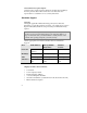
Warranty and Service U.S. Robotics Access Corp. Limited Warranty Your U.S. Robotics product is covered by a Limited Warranty. U.S. Robotics warrants that the product that you have purchased from U.S. Robotics or from a U.S. Robotics authorized reseller is free from defects in materials or workmanship during the Limited Warranty period, identified in the chart below, which is effective on the date of purchase. During the Limited Warranty period, U.S.
• Damage from repair or replacement of warranteed parts by anyone other than U.S. Robotics or a U.S. Robotics authorized service provider THIS LIMITED WARRANTY DOES NOT GUARANTEE YOU UNINTERRUPTED SERVICE. REPAIR OR REPLACEMENT AS PROVIDED UNDER THIS LIMITED WARRANTY IS THE EXCLUSIVE REMEDY OF THE PURCHASER. THIS LIMITED WARRANTY IS IN LIEU OF ALL OTHER WARRANTIES, EXPRESS OR IMPLIED, INCLUDING, BUT NOT LIMITED TO, ANY IMPLIED WARRANT OF MERCHANTABILITY OR FITNESS FOR A PARTICULAR USE OR PURPOSE. U.S.
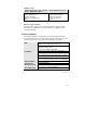
Area North America Phone No. 1-800-231-8770 (toll free) Monday - Friday 7. a.m. - 8 p.m. Central Standard Time Weekdays Time Time Zone Europe, Middle East, Africa 353-1-205-7700 All Other Locales 1-847-797-6600 Monday - Friday 9 a.m. - 7 p.m. Central European Time Monday - Friday 7 a.m. - 8 p.m. Central Standard Time What Information Should I Have Ready Before Calling For Support? To enable U.S.
Software/Firmware Update Options Customers who require Software/Firmware updates beyond 90 days from the purchase date will be referred to a U.S. Robotics sales representative to establish a service contract, if desired. Hardware Support Warranty During the applicable Limited Warranty period, if U.S. Robotics determines your product requires servicing, you will be given a Service Repair Order (SRO) number to help us track your Limited Warranty request.
Shipping Address North America and Locations Outside Europe, Middle East & Africa U.S. Robotics ATTN: SRO Receiving 1800 W. Central Rd. Mt. Prospect, IL 60056-2293 SRO#...................................... Europe, Middle East, Africa U.S. Robotics Services, Ltd ATTN: RMA Department 5 Richview Office Park Clonskeagh, Dublin 14 Ireland Hardware Support Options Customers who require out-of-warranty hardware support will be referred to a U.S.
viii
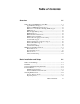
Table of Contents Overview 1-1 What’s New with NETServer 8/16 Plus ...................................... 1-1 AppleTalk Phase II Support ............................................................ 1-2 Enhanced SNMP Management Support.......................................... 1-3 RIP Version 2 and Classless Routing (CIDR) Support ................... 1-4 RTMP Support ................................................................................ 1-4 IPX and AppleTalk Spoofing.............................
Accessing the Configuration Interface ........................................ 2-9 Establishing Communications with NETServer Plus.......................2-9 Automated Quick Setup Programs.................................................2-10 Advanced Management Capabilities..............................................2-10 Command Line Interface Conventions...................................... 2-11 Hardware Installation ................................................................
IP Terminal Server Setup 4-1 Configuring the Remote Computer.............................................. 4-2 Configuring Login Hosts ............................................................. 4-3 Configuring Login Users ............................................................. 4-5 IP Terminal Service Case Study .................................................. 4-9 Network Dial In Access 5-1 Overview......................................................................................
Network Dial-Out Access 6-1 Overview ..................................................................................... 6-2 IP/IPX Dial-Out...............................................................................6-2 Telnet Dial-Out................................................................................6-3 Network Dial-Out Configuration Overview................................ 6-3 Network Dial-Out Configuration................................................. 6-4 Add Modem Groups ........
Configuring NETServer B ............................................................ 7-23 Packet Filters 8-1 Filtering Overview ....................................................................... 8-2 NETServer Filtering Capabilities.................................................... 8-2 NETServer Filtering Applications................................................... 8-3 Information Sources ........................................................................ 8-3 Filter Types .................
Using Ping .....................................................................................9-13 Using Echo ....................................................................................9-14 Viewing Interface Status, Settings .................................................9-14 Viewing Netserver Plus System Information .................................9-15 Displaying System Information................................................. 9-15 List Commands ...........................................
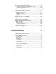
Supernet Example .........................................................................B-10 Supernetting and the NETServer...................................................B-11 IP Subnet Mask Address Table................................................. B-12 LEDs and DIP Switches C-1 LED Overview ............................................................................ C-1 Run/Fail LED.............................................................................. C-2 Modem Indicators ............
RADIUS Authentication and Accounting E-1 RADIUS Overview...................................................................... E-1 RADIUS Authentication................................................................. E-1 RADIUS Accounting ...................................................................... E-2 Obtaining RADIUS......................................................................... E-2 Performing Authentication ..........................................................
Chapter 1 Overview While the NETServer 8/16 Plus release nominally marks the latest upgrade in the NETServer V.34/I-modem family, it truly represents a new phase in product development by the introduction of a brand new code set. This development is a considerable departure from 3.x releases in how the NETServer command set works, with enhanced features and greater ease of use.
• Enhanced link-layer compression support • Enhanced RADIUS support • Improved security • Command line editing Each new feature is described generally in the sections below. AppleTalk Phase II Support Full support for AppleTalk Phase II is new in NETServer 8/16 Plus.
Enhanced SNMP Management Support NETServer 8/16 Plus includes full Windows-based SNMP version 1 management support that allows you to: • Configure the NETServer • Perform accounting functions • Generate SNMP traps.
RIP Version 2 and Classless Routing (CIDR) Support NETServer 8/16 Plus implements RIPv2, an extension of the original RIP protocol. RIPv2 adds the following capabilities to the original RIP protocol: • Subnet masks • Specification of next hop • Authentication • Multicast support Classless Inter-Domain Routing (CIDR) is a method for reducing the burden on routing tables in the Internet. CIDR provides a subnetwork for Internet service providers by combining a number of Class C addresses into one.
IPXWAN Support NETServer 8/16 Plus supports the IPXWAN protocol used by Novell to negotiate the WAN network number and the transmission delay over the link. IPX Dialout and Address Pools NETServer 8/16 Plus now supports dialout over IPX and the creation of address pools to conserve IP address usage. TFTP Download Capability You can use the Trivial File Transfer Protocol (TFTP) to download files to the NETServer Plus flash memory.
Enhanced Link-Layer Compression Support NETServer 8/16 Plus supports these link-layer compression methods: • STAC LZS - a compression mode that uses the LZS-based algorithm ( the most common PPP algorithm) • Microsoft PPC - a compression mode that differs slightly from STAC, utilized by Windows 95 and NT • Ascend - a compression mode based on STAC LZS with differences in the way initial sessions and dictionary resets are negotiated Enhanced RADIUS Support NETServer 8/16 Plus has the following RADIUS-r
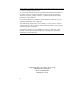
Generic filters - Protocol-independent filters can be used to filter packets based on their byte and offset values Command Line Editing The NETServer 8/16 Plus supports complete editing from command line including character, word and line deletion. NETServer 8/16 Plus Overview The NETServer 8/16 Plus is a multi-protocol, dial-up router and terminal server commonly described as a remote access server.
TTY (Terminal) Data Remote Office User PSTN/ ISDN NETServer Host Telnet, Rlogin ClearTCP Mobile User Host Figure 1.
Network Dial In Access NETServer 8/16 Plus provides dial-in network access for remote users. Remote IP, IPX, or AppleTalk networked users can dial in and attach to the local network as if they were local nodes. Packets transmitted over the dial-in connection are encapsulated using the following protocols: • PPP (Point-to-Point Protocol) • SLIP (Serial Line IP Protocol) • ARAP (AppleTalk Remote Access Protocol).
Dial-Out Access NETServer 8/16 Plus modem ports can be accessed by network PCs and workstations to provide users with dialout services. This allows network users to send faxes, connect to Bulletin Board Systems (BBS), information services such as CompuServe, or the Internet over a dial-up PPP connection. LAN users require an NCSI-compatible communications application to access NETServer Plus modems (see Chapter 6: Network DialOut Access for more information). See Figure 3 below.
LAN-to-LAN Routing NETServer 8/16 Plus performs dial-up routing between facilities. This occurs when one NETServer dials up another and logs in as a user, creating a NETServer - NETServer rather than a user - NETServer connection. See Figure 4 below. Connections can be set up in a number of ways: manual, ondemand, timed, and continuous. You can configure connections to use various routing and protocol parameters.
1-12 Overview
Chapter 2 Basic Installation and Setup This chapter describes what to do now that you are acquainted with NETServer 8/16 Plus functionality. Read the following sections appropriate to your unit and skip the rest. What’s in the Package The following checklist itemizes what you need before you can use NETServer 8/16 Plus. At installation, it is assumed the checklist was completed, so, check off the items now. It will make your installation and set up process easier and quicker.
❑ NETServer 8/16 Plus CLI Reference Guide ❑ NETServer Manager Plus diskette ❑ NETServer 8/16 Plus AT Modem Reference Guide ❑ Customer Support & Warranty/Registration cards ❑ PC Software Download (PCSDL) diskettes (2) ❑ Release Notes (readme.txt file) ❑ Stampede 4.0 Remote Office CD-ROM ❑ NCSI Client Diskettes (3) System Administrator Requirements This document assumes that you are familiar with Novell, IP and/or AppleTalk networks.
Network Solutions InterNIC Registration Services 505 Huntmar Park Drive Herndon, VA 22070 1-703-742-4777 For networks with only a few IP machines, you may be able to contact your local Internet access provider and let them handle the details. AppleTalk Reference Material For guidance on AppleTalk network administration, we recommend the Apple Communications Library's Apple Communications Technical series.
BRI works over the same wiring that is in place for analog telephone lines. The difference is in the equipment you attach and signaling used. ISDN Basic Rate Interface Physical Appearance At your site, the ISDN lines will use RJ45 wall jacks and cables, each of which, in ISDN, make up the S/T interface. RJ45 connectors have 8 pins. See Figure 1 below. The connectors, or cables, for attaching the NETServer Plus modems to the jacks installed by your service provider are in the package. Figure 1.
B- and D-channels BRI typically contains three channels. These channels are created using complex signaling techniques. Usually BRI is made up of two 64 kbps B (bearer) -channels and one 16 kbps D (delta) -channel. The B-channels carry data or voice traffic. The D-channel is used for call control: the setting up and tearing down of calls. See Figure 2 below. Figure 2.
The NETServer routing engine is a completely separate device from any of the I-modems. Its job is to route data from its ports (all B-channels of all internal I-modems) to its LAN (Ethernet) interface and vice versa. However, it is also able to configure and use the internal I-modems to establish connections with remote devices. See Figure 3 below. Figure 3.
The U.S. Robotics I-team The I-team is a group within USR’s Customer Support department that provides ISDN ordering and configuring assistance. The I-team helps you determine availability and pricing of ISDN service in your location, installation costs. They also determine lead time for installation and will help coordinate the configuration of the telephone company’s equipment, so your NETServer Plus I-modem will work properly.
• Dynamic TEI assignment • RJ45 connector preferred (RJ11 is acceptable) 2 Specify your preferred long distance provider. 3 Ask the type of central office switch at which your ISDN line will terminate, and which protocol controls your calls. ❑ If your switch is AT&T 5ESS, running National ISDN-1 or Custom, request Terminal Type A.
Accessing the Configuration Interface This section explains how to attach to the configuration interface locally via the console port or remotely via the NETServer Manager Plus.
platform you’re using, you may need to modify a configuration file for VT100 settings. Automated Quick Setup Programs As an alternative to the manual configuration described in this manual, NETServer Plus offers two easy, automated configuration programs (described below) to quickly and efficiently get your unit up and running.
information. Filtering, using the Trivial File Transfer Protocol (TFTP), and spoofing, are two other management tools provided. Spoofing is supported when two NETServers are connected only. Command Line Interface Conventions The NETServer Plus’ Command Line Interface (CLI) is an interactive application that allows you to view information and set system parameters. This section provides general information about CLI command conventions and usage.
Double quotations distinguish strings If you want to include white space or special characters in a text string, the string must be enclosed in double quotes. Command syntax and CLI rules This document uses the following CLI command syntax conventions: • Keywords are in bold text. For example: ping • Values following keywords are in brackets. For example: [interval] • Values that are position dependent and do not have keywords are in arrows.
( For example, if you type add ip n and press , command completion will spell out the keyword network without losing your place in the command syntax. If the keyword is not unique, you will get an error message. Command retrieval & & You can call back a n earlier command by pressing p (Ctrl p). You can also use n (Ctrl n) to move forward to the next command. Command retrieval works by consulting the history of previous commands entered, which defaults to the last ten commands.
NETServer provides a cursory list of associated commands and their proper syntax. You can also get positional help while entering a command by typing a question mark. The CLI displays possible completions and returns the cursor to the last point in the command before you entered the question mark. First disable, then delete process Many delete commands require that you first disable the process or function.
Using add and set commands You can use the add and set commands to set and change system parameters. These matched commands are functionally related, but also differ dramatically. Table entries such as user, interface, network, etc., require that you use the add command to set the initial parameters. You can then use the set command to change parameters that have been added. Using list and show commands You can use the list and show commands to view table entries or detailed table entries.
Note: For desktop and rack mounting: * DO NOT block the fan on the right side of the unit. * Keep the unit in a dry place at room temperature. * Keep the unit face up and level - don’t stand it on its side. Installing on the Desktop Carefully remove the NETServer Plus from the box and attach the four rubber feet (supplied) to the recesses in the bottom of the unit. The bottom panels of V.34 and I-modem units are similar. See Figure 4 below. Figure 4.
2 Gather four sets of nuts, bolts, and other mounting hardware appropriate for your rack. 3 Holding the unit in the rack and supporting it from underneath, insert each screw into the rails of the equipment rack and loosely attach the corresponding nuts/anchors. See Figure 6 on page 2-18. Figure 6. 4 Screw/rail mounting Once all 4 screws have been inserted, tighten beginning with the two bottom screws.
Cabling Examine the NETServer Plus V.34 back panel illustration below for cable installation. The I-modem back panel offers similar functionality but I-modem, network and console ports may be arrayed differently. See Figure 7 below. Figure 7. Cable connections 2-18 1 Be sure the NETServer is turned off. Plug one end of the power cable into the power connector on the NETServer and the other end into a grounded AC outlet or power strip. 2 Attach the type of cable that is appropriate for your network.
Note: You may want to install a line noise filter/surge protector between the power source and the NETServer. This protects the NETServer and the data stored in it. Setup to Talk to the NETServer 8/16 Plus 1 Attach the provided serial cable to the Console port. See Figure 8 below. Figure 8. Console/null modem cable connection 2 If you want to dial into the Console port, attach a modem directly to the other end of the serial cable.
your communications software for 8 data bits, no parity and 1 stop bit. 4 Examine the back panel of the NETServer. Find the lower bank of dip switches (next to the NETServer Configuration description) . Set DIP Switches 1 and 2 to a baud speed setting of your choice. See Figure 9 below for options. 1 2 9600 bps 1 2 19800 bps 1 2 38400 bps 1 2 57600 bps Figure 9.
Do you want to continue with NETServer Quick Setup?__ There are two ways to proceed: You can set up only the basic configuration, which will allow you to continue with the Windowsbased Access Manager. Or you can configure a simple configuration for both the LAN and WAN of IP, IPX, and AppleTalk. Do you want to configure only enough to use the GUI based system [yes]?___ Please answer the following questions with "yes" or "no" to indicate which portions of the system you want to configure.
>>> What SNMP community will manage this system [public]? ____________ Along with a community name, you need to give the IP address of the system using that community. "0.0.0.0" means any system. >>> What is the address of the station for this community [0.0.0.0]? ____________ You also need to specify if this community can only read information, or read and write information.
>>> Would you like to set up radius authentication [yes]?__ >>> Enter the IP address of the primary radius authentication server [n.n.n.n]? ___________ >>> What is the shared secret with this server []? _______ Quick Setup IP information The NETServer uses a network name to identify the network for future management commands.
>>> What metric should be applied to the default gateway [1]? ___ >>> Do you want to configure DNS for this Netserver [yes]? >>> What is the address of the main DNS server for this Netserver [ ]? ________ >>> What is the default DNS domain name for this Netserver [ ] ? _____________ You can either assign each user his or her own address or you can set aside a pool of addresses for dynamic allocation. >>>Do you want to set up an address pool [yes]? __ The address pool is a continuous range of addresses.
You need to specify the framing for the IPX network. It should be one of the following: "ethernet_ii", "snap", "dsap", "novell_8023." >>> What is the framing for the IPX network [ethernet_ii]? ___ You can either assign each user his or her own address or you can set aside a pool of addresses for dynamic allocation. >>>Do you want to set up an address pool [yes]? __ The address pool is a continuous range of addresses.
>>> Enter the end of the network range of the other router [ ] : _____ Would you like to review your current settings before executing [yes]? __ Identification Information: System Name: ____________ System Contact: ____________ System Location: ____________ Management Information: Console Login:: ____________ SNMP Management: SNMP Community: ____________ SNMP IP Address: ____________ SNMP Read&Write: ____________ TELNET Management: User name: ____________ Password: ____________ Syslog Dae
IP Frame Type: ____________ IP Def Gateway Addr: ____________ IP Def Gateway Metric: ____________ DNS Server Information: DNS Server Address: ____________ DNS Server Domain Name: ____________ IP address pool: ____________ IP pool address: ____________ IP pool size: ____________ IP WAN Information: TFTP Client Information: TFTP Access: ____________ IPX Information: IPX Network Name: ____________ IPX Network Number: ____________ IPX address pool: ____________ IPX pool address: _______
Setting Up the I-modems Unlike V.34 modems, each I-modem must be configured before you can use them. Follow the steps below. 1. Taking the information given you by your local telephone company, specify the interface name (mod:1, mod:2, etc.) , switch protocol type, SPIDs and directory numbers. Note: If you check the back panel, you’ll notice there are two interfaces per connector.
4. Reset each I-modem by issuing an ATX! command. Your new configuration won’t take effect until you do so. Type: set imodem interface mod:1 at_command ATZ! - When the LEDs start blinking green, an ATI12 command is sent to the I-modem, responding with a configuration report. Watch the I-modems’ LEDs closely.
To begin manual configuration: 1. Power on the NETServer. The "NETServer>" prompt appears. When you’re prompted by the Quick Setup Program to continue, type: no 2. Name your NETServer and specify additional system information. The name you enter serves as the NETServer's DNS name and SNMP system name. The name will also be the name that the NETServer advertises in SAP broadcasts. The name must be unique - no other device on your network can share it.
4. Optional. If you plan to use an SNMP application to configure and manage the NETServer, you must specify SNMP community values. SNMP community names segregate administrative management groups and should match the community settings of your generic SNMP software.
Important: Even if your network uses only the IPX protocol, you must still set up an IP address for the NETServer if you want to use our NMP or an SNMP later. IP Configuration To manually configure the NETServer's LAN interface on an IP network: 1. Enter IP Network information. The network address consists of the station address and a subnet mask using this format: nnn.nnn.nnn.nnn/A, B, C, H, 8-30 or nnn.nnn.nnn.
Note: To verify your network settings, use the list networks command. You can also check the connection by using the ping command. 2. Set a default gateway. If the NETServer does not know where to send a packet, it forwards the packet to the default gateway or router addressed in this step. Default gateways must be on the same subnet as the NETServer. You also need to supply a metric (hop count) for each type of default gateway. Possible values range from 1 (default) to 15.
below but you must also specify the order you prefer they be employed. This value is the preference number. Type: add dns server preference address For example: add dns server preference 1 address 192.75.222.182 - Note: The DNS server is only consulted to resolve host names not found in the hosts table. If you are using a name service, the hosts table may be left empty. Also, you may use the resolve name command to learn DNS host names or numbers.
IPX Configuration To configure the NETServer's LAN interface on an IPX network, you must: • Determine the IPX network number • Set the NETServer IPX parameters Important: Even if your network uses only the IPX protocol, you must still set up an IP address for the NETServer if you want to use our NMP software or SNMP application later.
A display similar to the one shown below appears: File server name: USR_SERVER_ONE IPX internal network number: 0000000A Western Digital Star EtherCard PLUS Driver v2.05 (910424) Hardware setting: I/O Port 300h to 31Fh, Memory CC000h to Cffffh, Interrupt Ah Node address: 0000C0488D28 Frame type: ETHERNET_802.3 Board name: TENBASE_802.3 LAN protocol: IPX network 00000255 Western Digital Star EtherCard PLUS Driver v2.
A display similar to the one shown below appears: LAN A Configuration Information: Network Address: [0788] [002608C0D53F4z] Hardware Type: [3Com 3C505 EtherLink Plus (Assy 2012 only) V2.30EC (880813)] Hardware Setting: IRQ=5, IO=300h, DMA 5 The above example only has one frame type, so the network address is 0788. 4. Jot down the network address for a frame type you’ll use. Setting IPX Parameters To configure the NETServer's LAN interface for an IPX network: 1.
Note: To verify network settings, use list networks command. 3. Save your work by typing: save all - AppleTalk Configuration Important: Even if your network uses only the AppleTalk protocol, you must still set up an IP address for the NETServer if you want to use our NMP program or SNMP later. To configure the NETServer's LAN interface for an AppleTalk network: 1. Specify network information. The address range is the range of nodes from start to end address, expressed as .
3. Enable the network by typing the following command: enable appletalk network For example: enable appletalk network pixie - Note: Verify network settings with list appletalk networks. 4. Save your work by typing: save all - Configuring a Manage User This section describes how to create an administrative user with manage privileges to establish a secure, centrally administered NETServer.
Network example: add user predator password aliens type manage,network Login example: add user predator password aliens type manage,login 2. - - Save your work. save all - Manually Configuring the WAN Interface Setting up a protocol over the WAN begins by creating and editing a user profile. With the user profile you can specify the call type, protocols, addresses, and bandwidth management parameters that determine how you connect and communicate to that user (remote site) over the WAN.
Chapter 3 Configuration Overview The NETServer 8/16 Plus lets you manage and configure the NETServer by typing commands. The configuration information that you set using these commands is stored in a number of tables that reside in the NETServer flash memory.
Configuration Command Overview NETServer configuration data is stored in several tables, (User and Interface tables, e.g.). You can change most parameters in these tables using the generic set command: set [user | interface | system | etc.] For example: set user maximillian message “Mexico is Mine” Most objects, like interfaces and users, must be created before they can be configured.
Configurable Table Overview This section briefly describes some of NETServer’s internal databases, or tables, which contain configuration information. Interface Table This table contains information about all NETServer interfaces, including modem ports and the Ethernet interface. User Table This table contains authentication and configuration information for five types of users: Login, Network, Callback, Dial out, and Manage users.
Facilities Table You can check the this table to judge system performance. The Facilities Table contains each NETServer event facility and its associated log level. Each facility generates unique event messages during processing which can be sent to a syslog server you define. Facilities are configurable in that you can change log levels from the defaults shown below. Available log levels are: debug, verbose, common, unusual and critical, with critical being the most severe event.
Network Table This table contains all generic protocol information entered through the add (ip, ipx and appletalk) network command. Filter and Associated Tables Filters may be created to control packets you permit to pass through given interfaces. You can create filters that work on a per-user or per-interface basis. Filters that you create are stored in the Filter Table. Also, the Access Filter Table determines whether user filters take precedence over interface filters.
Syslog Table This table contains IP addresses of syslog hosts to which event messages are sent. You can define multiple syslog hosts that record event messages by the message's log level.
Chapter 4 IP Terminal Server Setup Remote users can dial into the NETServer 8/16 Plus to establish a terminal session with a host on the local network using a login service such as Telnet, Rlogin, or ClearTCP. See Figure 1 below for a sample network topology. TTY (Terminal) Data Remote Office User PSTN/ ISDN NETServer Host Telnet, Rlogin ClearTCP Mobile User Host Figure 1. .
Configuring the Remote Computer Remote terminal users are known as login users in the NETServer system.
Configuring Login Hosts For a login host to be available to a login user, you must define it in the NETServer login hosts table. This table contains the host name, address, selection preference, and login service port for each login host. Note: To allow the user to access a login host using a host name, you must first configure a DNS server using the add dns server command. For example: add dns server 7.7.7.
Rlogin Port Optional. The Rlogin port number of the host. Telnet Port Optional. The Telnet port number of the host. ClearTCP Port Optional. The ClearTCP port number of the host. For example: add login_host detroit address 6.6.6.6 preference 1 Step 2 - Check Your Work Check you host entries using the following command: list login_hosts Each login host you add that includes a name and IP address is also added to the NETServer DNS host table.
Configuring Login Users Remote login users can use login services such as Telnet, Rlogin, or ClearTCP by dialing into the NETServer. Login users can connect directly, or be configured as callback users, meaning the NETServer will call the user back at a phone number specified in their user profile. You can configure the user to use a specific login service and access a specific login host, or you can configure the user to determine the login service and login host.
Rlogin Although Rlogin was originally a UNIX protocol, it is now supported by some nonUNIX machines as well. Unlike Telnet, Rlogin allows a user logged into a host to access their accounts on other (trusted) hosts without re-entering a password. ClearTCP Unlike Telnet and Rlogin, ClearTCP is not actually a login service, it is a direct connection to a given TCP port number. 8-bit data is exchanged without interpretation. Note: The host type setting may override this setting.
Step 2 - Configure Login User Parameters Use the following command: set login user host_type [prompt | select | specified] login_host_ip_address login_service [rlogin | telnet | cleartcp] tcp_port terminal_type Host Type Determines how the user is connected to a login host. The default is select. prompt If the user is prompted, this setting overrides the login service setting.
TCP Port Optional. If the login host uses a TCP port number other than 23 (the default for Telnet), you can set the TCP port number using this command. For ClearTCP connections, make sure that the host's TCP port number matches the TCP port number you enter here. Terminal Type Optional. Set the terminal type for the remote connection. The default is VT100.
IP Terminal Service Case Study This section provides an example how to configure a login user to dial-in to the NETServer and establish a Telnet session with a host machine on the network. The user will be prompted for the login service and host address. Figure 2 below depicts the remote terminal connection for a user named Jack to the corporate LAN. Jack's home computer uses VT100 terminal emulation software to establish a IP terminal session with any host on the LAN that he is authorized to access.
Assuming that a DNS server is already configured for the NETServer, follow these steps to configure the login host and login user: 1. Add a user called jack with the password agent86 that is a login user type. add user jack password agent86 type login 2. The login host that Jack will access has not been added yet. This host is the one that most users will be logging into on a daily basis, so set the preference to "1". add login_host quartz address 195.112.133.2 pref 1 3.
Chapter 5 Network Dial In Access The NETServer 8/16 Plus allows remote PC and Macintosh users to dial in over analog or ISDN lines and connect to the local network.
Figure 1 below depicts the NETServer's remote network access capabilities. Internet Remote Office User PPP, SLIP, or ARAP PSTN/ ISDN NETServer PCs IP, IPX, and AppleTalk Mobile User File Server RADIUS Server Figure 1.
Overview This section describes how to set the NETServer up to provide remote access services to dial-in network users. Configuring the NETServer for dial-in access simply involves setting up a network user profile for each remote user. The network user profile contains all of the information necessary for the user to connect to the network, such as protocols, remote addresses, and other unique settings.
IPX Parameters You can configure the user profile to specify a unique IPX network number that will represent the link between the remote system and the local network for the duration of the connection, or you can configure the NETServer to assign an IPX network number from a pool. You should know: • IPX remote access sessions must use the PPP protocol.
Remote Computer Setup The remote user’s computer must have a modem or ISDN connection and communications software that supports the remote access protocol that they are using (PPP, SLIP, or ARAP). A protocol driver must be loaded on the remote user’s computer for these types of connections.
Configuring Address Pools If you want network users to be assigned an IP or IPX address from a pool each time they connect, you must configure address pools on the NETServer. Configuring an IP Address Pool To configure an IP address pool: 1. Set the initial pool address: set ip system initial_pool_address 2. Set the number of pool members. The maximum is 8 or 16, depending on the number of ports your NETServer has. set ip system pool_members For example: set ip system init 195.
Configuring an ARAP AppleTalk Address Pool While a NETServer configures an ARAP AppleTalk address pool by default, you can set a desired range of network numbers to be included in this pool. For example, the default value of 0 0 can be changed to 1 - 1, allowing a user to be assigned a node from network 1. The ARAP node network must be a subset of the range defined for the LAN. 1.
NETServer Defaults A remote access user is defined as a network user in the NETServer database. When you create a network user, the NETServer builds an extensive user profile that includes many default parameters. These defaults reflect most common types of user configurations. This makes user configuration easier, as you may only need to change a few parameters from their default settings. Note: When you add a network user, IP and IPX protocols are enabled by default.
Configuring an IP User To configure an IP user: Step 1 - Add the User Create a standard network user, specifying the user's password, type, and default network service. Use the following command: add user password type [network | login | callback] network_service [slip | ppp] Password Unique user password.
Tip: At this point, it may be helpful to use the show user command to display the user's default parameters. This allows you to decide which parameters you need to set, and which parameters you can leave as defaults. For example, to add a network user employing PPP over IP, type: add user kay password howe type network network_service ppp Step 2 - Specify a Remote Address If you want to explicitly specify the network user's remote IP address, follow the instructions in this step.
Step 3 - Set the Address Selection Method If the network user's address is not specified, you need to define whether the user's remote IP address is assigned or negotiated: set network user address_selection [assign | negotiate | specified] assign Configure an IP address from the IP address pool, which is set globally using the set ip system command (see Configuring an IP Address Pool on page 5-6) negotiate PPP connections only. The remote computer must have an IP address configured.
Configuring an IPX User To configure an IPX user: Step 1 - Add the User Create a standard network user, specifying the user's password, type, and default network service. Use the following command: add user password type [network | login | callback] network_service ppp Password Unique user password.
Step 2 - Specify a Remote Address If you want to explicitly specify the network user's remote IPX address, follow the instructions in this step. If you want the remote IP address to be selected from a pool or negotiated, go to step 3. Use the following command: set network user ipx_address For example: set network user glenn ipx_address 100 Note: If the IPX address specified in a user's profile is in use when the user dials in, the call will be dropped.
Step 4 - Configure IPX Routing Configure how you want the NETServer to handle IPX RIP and SAP packets. The default is RESPOND.
Configuring an AppleTalk User Unlike IP and IPX, AppleTalk dynamically assigns a station address for the remote computer. An AppleTalk dial-in connection is treated as an extension of the local LAN. The NETServer negotiates a station address on the dial-in user's behalf (AppleTalk station numbers are dynamic) and provides a proxy-AARP service on the LAN. Note: RADIUS does not support AppleTalk user authentication. You must configure an AppleTalk user locally.
Step 2 - Set the AppleTalk Range Specify the range of addresses within your LAN network range that you want to make available for the remote connection: set network user range_appletalk_address Step 3 - Disable Zone Filtering (optional) This setting determines the AppleTalk zones that the remote user will see. By default, AppleTalk zone filtering is enabled, which means that zone filtering occurs based on filter rules that you defined in the filter file.
Configuring PPP Parameters If the remote user connects using PPP, you can also define several PPP parameters that control how the remote access session is handled. Note: This section describes only the parameters that are applicable for network dial-in users. Many of the configurable PPP parameters are used for LAN-to-LAN routing only. These parameters are described in Chapter 7, LAN-to-LAN Routing.
Reset Compression Mode Determines how often PPP should examine packets to decide when to re-negotiate the optimum compression algorithm. Default: auto. Transmit Asynchronous Character Control Map Determines whether the NETServer uses the asynchronous control character map to filter outgoing data. Default: ffffffff. Configuring Additional Parameters In addition to the protocol-specific parameters that you configure for IP, IPX, and AppleTalk, you can also set several standard network user parameters.
Change the authentication setting by typing: set ppp receive_authentication [chap | pap | either | none] Phone Number If the network user is a callback user, use the following command to set the user's phone number. Note: this value does not apply to other dialin users. set user phone_number Remote Access Case Study In this case study, three network users are configured, one for each protocol supported by the NETServer.
• All necessary protocols are enabled • All other settings remain at factory defaults Configuring User_A To configure User_A: 1. Add a user called "User_A" that is a network/callback user type (the password is the same as the user name): add user User_A password User_A type network,callback Note: The default network service for any network user that you add is PPP. Therefore, there is no need to set the network service parameter for this user. 2.
1. Add a user called "User_B" that is a network user type (the password is the same as the user name): add user User_B password User_B type network Note: The default network service for any network user that you add is PPP. Therefore, there is no need to set the network service parameter for this user. 2. User_B's IPX address will be assigned from a pool.
5-22 Network Dial In Access
Chapter 6 Network Dial-Out Access NETServer 8/16 Plus modem ports can be accessed by network PCs and workstations to provide dialout services. This allows network users to send faxes, connect to Bulletin Board Systems (BBS), information services such as CompuServe, or the Internet over a dial-up PPP connection. PSTN/ ISDN Dial O t Modem Connection NETServer PCs IP, IPX, Telnet Figure 1.
Overview The NETServer provides these network dial-out services: • IP/IPX dial-out • TELNET dial-out IP/IPX Dial-Out IP/IPX dial-out is commonly referred to as modem sharing, meaning that any number of NETServers installed on your network can provide network users with quick access to a modem connection.
NCSI provides a network naming service that allows you to name each NETServer on your network, as well as the ability to name ports by both the type of service they perform (for example, MODEM) and by a specific name (for example, PORT01_NS1). The user can then select a specific NETServer, service, modem group, or modem port from a list. A modem port is made available to the user. If authentication is required on that port, the user is prompted for a login name and password.
Network Dial-Out Configuration Add Modem Groups By default all modem ports on your NETServer belong to a default modem group called all. However, you can define several modem groups that contain any number of interfaces. Modem interfaces can belong to more than one modem group. When a network user requests the use of a modem group, he or she will be assigned the first available modem from that group.
To specify a modem group, the data parameter uses this format: data modem_group= Note: If any data string value includes a space, enclose it in double quotations and forward slashes. For example: data modem_group=\”boston crew\” See the CLI Reference Guide for more information.
Telnet users If you want to TELNET to a NETServer modem and have already added a modem group and dialout user, you must configure network service as follows: telnetd as server_type, a socket number above 1024 (to avoid conflicts with existing socket numbers), and DATA parameter type=dialout, at a minimum. Optionally, you can set a login banner or login prompt as follows: • login_banner= • login_prompt= If you don’t want this user to require authentication, add auth=off to the data values.
Or from the WIN95 Run dialog box, type in the Open field: telnet 199.56.203.5 6666 You’ll be prompted for login and password and after a moment you can issue AT commands to the modem. Note: Callers with the data value auth=off are not prompted to login after authentication. For example: atdt18479825092 Note: The modem LED lights only when you dial out, not before. Editing Network Service You can change network service values using the set network service command.
PC Client Software Installation and Setup The NPC Client Setup program is designed to run on any LAN workstation using the Novell IPX protocol connected to a NETServer. See the appropriate section listed on the following pages for procedures to set up on various platforms. WARNING: Before installing or running NPC Client programs, make sure that Novell’s VLM environment is loaded beforehand. Issuing the NCSI command in a non-VLM environment may cause your system to lock-up.
For either method, first load the TSR program. 1. Load the TSR (Terminate and Stay Resident) part of the Client program. This is done by issuing this command: ncsi - Once the NCSI software is loaded, your screen will display a message similar to the one shown below, which includes the version of NCSI and the sub-network version. Network Communications Services Interface (NCSI) Ver: 1.22.
Now you can choose to establish an IPX Dial-out session in 2 one of two ways. To use NPC’s NTERM program, go to Step 2. To go to a DOS prompt, skip to Step 3. 2. Load the terminal emulation software by typing: nterm - 2 This brings up the NTERM program’s Main Menu. You can configure the terminal emulator by pressing the key while the Main Menu is active. This context sensitive option will allow you to add or delete stored configurations and save any changes you make.
NPC DOS Command Overview The following table shows basic NPC DOS commands. Command Purpose Syntax (how to use it) - NCSI.exe This command loads the DOS TSR. (Terminate and Stay Resident) program. At the ncsi:\> prompt, type ncsi and press . NCSI_REL.exe This command removes the DOS TSR from memory. At the ncsi:\> prompt, type ncsi_rel and press . CLIST.exe This utility is used to view the NETServer and display all available modems (devices) in the NETServer.
NPC Client Installation for Windows 3.x To install the NPC Client software for Windows 3.x: 1. Start Windows and go to the Program Manager screen. 2. Insert the NPC Client for Windows 3.x Installation diskette in the floppy disk drive. 3. Click File, then click Run. At the Run command line, type: a:\setup.exe - 4. Click the Install button, and click on Yes at the Install NCSI for Novell based Networks prompt. Accept the default directory of c:\ncsi or enter a specific directory.
8. Return to and exit Windows, then reboot your client workstation. After Windows has been restarted, proceed to the next section explaining setup and use of NCSIPort. NCSIPort for Windows 3.x Program Setup Before you setup NCSIPort for Windows 3.x, there are three items you should check concerning your Windows configuration: • The IPX version of NCSI requires extra dynamic sockets in order to function properly when file and printer sharing is enabled.
To setup the NCSIPort program: 1. In Windows, double-click the NCSIPort icon. The current status of your communications ports will be displayed. Click on the Ports option and select the port that you want to re-direct to NCSI. This NCSIPort option screen is shown below. A check mark (√) will appear beside either the word Local or NCSI, depending on whether the assigned port is to be re-directed or handled by the Windows communication driver. 2. Click on NCSI so the selected COM Port will be re-directed.
5. To test your setup, load the Windows Terminal program found in the Accessories group. Set the communications port to the re-directed COM Port and click on Ok. You should now see a blinking box. - Type at&f, press , and you should get an OK response. This response means that NCSIPort is configured correctly and ready to be used. Click on Phone, then click on Hangup to disconnect. Then, click on File and click on Exit to end this test. Using NPC’s Client for Windows 3.x Once NCSIPort.
4. Remove the Installation Diskette, click on the Restart option to restart your computer and Windows 95. Note: You must reboot Windows after the NCSI software has been installed. Do this before setting up NCSIPort. 5. Go to the NCSIPort for 95 Program Setup section below. NPC’s NCSIPort for 95 Program Setup NCSIPort for 95 is the 32-bit Windows application that redirects communications calls to NCSI.
7. In the NCSI program group, click Port Setup for NCSIPort 95 option to select a specific port on NETServer. Selecting a General name is not supported. When you select a specific name option, the screen displays as follows. Be sure to scroll down to the NETServer port you specified in the earlier configuration, otherwise NCSI may fail.This completes installation of the NCSIPort for 95 driver. Click on Save.
Opening an Application You can open a NCSI on non-NCSI compatible communications application to use the dialout client. But, Windows BTTY is provided as part of the dialout client software. Opening a non-NCSI Compatible Application You can open a non-NCSI compatible application to use the dialout client. Follow the instructions provided with the nonNCSI compatible application. Opening a NCSI-compatible Application You can open an NCSI-compatible application to use the dialout client.
3 You will be returned to the BTTY main menu. Click on Action, and Connect in the pop-up screen. When OK displays at the screen, you have successfully connected to NETServer 8/16 Plus. For a complete list of commands available using BTTY, select HELP from the menu bar. Note: Windows 95 has a feature that disables whatever protocol you are using over a Dial-Up connection on the Local Area Network.
An Overview of NPC’s Windows-Based Options Option NCSIPort and NCSIPort 95 Purpose These COM Port re-directors re-route Windows communications calls to the NCSI driver. This allows 16-bit Windows applications that are not NETServer aware to access the NCSI interface. NCSIPort 95 supports 16 and 32-bit applications. Windows Btty Allows you to connect to the first available idle device dial-out port and issue AT commands to that modem or dial-out port.
Chapter 7 LAN-to-LAN Routing The NETServer can perform IP, IPX, and AppleTalk LAN-toLAN routing with a remote NETServer or third party router over analog or ISDN lines. Note: This chapter assumes that the basic installation of all involved routing devices has already been performed, and that networks on the LAN (Ethernet) side of the NETServer have been configured. Figure 1 depicts a typical LAN-to-LAN routing scheme using two NETServers. LAN A LAN PSTN/ ISDN NETServer NETServer A Figure 1.
LAN-to-LAN Routing Overview The concept of NETServer users is not limited to end users who connect to the NETServer from a terminal or PC. You can also configure users that represent remote routing devices. The remote routing device and the NETServer work together to create a LAN-to-LAN routing link over analog lines, or with the NETServer I-modem, over ISDN or analog lines. A remote routing device is defined as a network/dialout user in the NETServer system.
Dynamic Routing Settings When the NETServer establishes a remote connection to an ordinary user (i.e., a user endstation) it is usually not necessary to send periodic router updates such as RIP, SAP, and RTMP messages. However, during a LAN-to-LAN connection, when the NETServer's remote connection is to a routing device, these messages may be needed. The NETServer can be configured to send and receive these messages on a per "user" (router) basis for IP, IPX, and AppleTalk protocols.
Note: Some routing devices have an IP address assigned to each interface rather than just one IP address for the entire device. If this is the case with the remote device, use the address of the interface you want to connect to. • The remote access protocol (PPP or SLIP) the NETServer will use • The remote system’s netmask • The MTU for PPP is 1500, and is negotiated between the client and the NETServer.
Static Routes Static routes are user-defined. By adding entries to the Routes Table, you tell the NETServer how to forward packets bound for specific networks. Dynamic Routes Fortunately, most networks do not require you to build routing tables by hand. All IP, IPX, and AppleTalk networks can use a dynamic routing protocol that builds routing tables dynamically to reflect changing network conditions.
How Packets are Routed When the NETServer receives a packet, it looks up the packet’s destination in its routing table. If a static route is found, the packet is sent to the gateway listed. If a static route is not found, the NETServer will use a dynamic route. If the routing table contains no routes to the destination, it will send the packet to the default gateway. If no such gateway has been defined, the packet is discarded.
Authentication The NETServer supports auto-detecting the PAP and CHAP methods of login authentication on PPP connections. Note: The NETServer also provides comprehensive RADIUS authentication support for PPP connections. For more information on using RADIUS to provide authentication services, refer to Appendix E, RADIUS Authentication and Accounting.
The challenged system then concatenates the challenge value with the shared secret and passes the new string through a hashing algorithm. When the hashing algorithm has formed a response based on this string, the challenged system replies with a packet containing both the response value and a user name. The authenticating host looks up the correct password for the user name received and then performs the same calculations the client performed, comparing the result to the response value received.
Password Unique user password. Type A LAN-to-LAN user is always a dialout and network user type, since the NETServer will be dialing out to the remote router and performing framed network services. Tip: At this point, it may be helpful to use the show user command to display the user's default parameters. This allows you to decide which parameters you need to set, and which parameters you can leave as defaults.
AppleTalk Enables or disables AppleTalk. The default is enable. Step 3 - Specify a Remote Address Unlike a remote end user connection, you must specify a remote address for the type of LAN-to-LAN connection you are configuring. You can use an un-numbered interface or a numbered interface: • un-numbered interface - uses the address of the unit itself.
Step 4 - Set the Remote Device Phone Number Specify the remote device's phone number using the following command: set user phone_number You can also specify an alternate phone number that the NETServer will dial if it cannot connect using the primary phone number.
Manual (Used for debugging) The NETServer dials out only when it receives a dial command from the command line. Continuous The NETServer will attempt to maintain the connection at all times. If the connection is broken it will dial again. Start Time Specifies the time to start a timed connection. The default is 00:00:00. End Time Specifies the time to end a timed connection. The default is 00:00:00. Modem Group Specifies which pool of modems will dial out to the remote location.
Step 6 - Configure Routing Parameters Routing parameters determine how to handle router specific parameters (spoofing, IPX WAN) and periodic router updates (RIP, SAP, RTMP). Use the following command: set network user rip [ripv1 | ripv2] ip_routing [listen | send | both | none] ipx_routing [listen | send | all | respond | none] ipx_wan [enable | disable] spoofing [enable | disable] header compression [none | tcp/ip] RIP Specifies the RIP version used. The default is RIPv1.
IPX Routing Sets the level of IPX RIP messaging that the two devices will exchange during the connection. The default is none.
Step 7 - Configure Dialing Scripts You can configure up to six send scripts and six reply scripts for the connection. Send and reply scripts specify modem commands required to establish and terminate the remote connection.
Channel Expansion Indicates the channel expansion percentage. When the amount of usage of the first channel exceeds this percentage, PPP will add the second channel. The default is 80 percent. Compression Algorithm Specifies which proprietary compression algorithm PPP should use. The default is auto. Expansion Algorithm Specifies which type of expansion algorithm should be used to decompress incoming PPP data. The default is linear.
Step 9 - Configure PAP/CHAP Authentication Parameters You can set PAP and CHAP-related authentication parameters using the following commands: set ppp receive_authentication [chap | pap | either | none] set system transmit_authentication_name set network user send_password PAP or CHAP Authentication By default, the NETServer is configured globally to use either PAP or CHAP authentication for PPP connections.
LAN-to-LAN Routing Case Study This section provides an example how to set up two NETServers located on separate LANs to perform LAN-to-LAN routing over a dial-up PPP link. The diagram below depicts two LANs connected by two NETServers: NETServer A and NETServer B. This configuration will enable IP, AppleTalk, and IPX protocols to be routed across a standard PPP link. Note: Many of the commands and keywords shown in this case study are abbreviated.
Assumptions This case study assumes the following: • NETServer A's sysname is netserv_a • NETServer B's sysname is netserv_b • NETServer A is on LAN1, the main data center of the company • NETServer B is on LAN2, a branch office • NETServer A will establish an on-demand connection to NETServer B • If traffic on the connection becomes too great, NETServer A will open a second line (this configuration will use the default channel expansion value) • If there is no traffic on the connection for 30
Configuring LAN Networks Follow these steps to establish IP, IPX, and AppleTalk networks on NETServer A's LAN interface (eth:1): 1. Add an IP network called "ipnet-1" with the class C IP address 192.112.226.1, ethernet_II frame type on interface eth:1: add ip net ipnet-1 addr 192.112.226.1/c frame eth int eth:1 2. Add an IPX network called "ipxnet-1" with the IPX address "7", ethernet_II frame type on interface eth:1: add ipx net ipxnet-1 addr 7 frame eth int eth:1 3.
2. Set the user's remote IP address to 78.0.0.2 with a class A address mask: set network user netserv_b remote_ip_addr 78.0.0.2/a Note: Alternatively, you can do an unnumbered IP network setup by specifying the IP address of NETServer B (192.112.227.1). If you do this, you can skip step 3 below. However, the NETServer does not support unnumbered IPX and AppleTalk addresses over a WAN link. 3. Set user's local IP address to 78.0.0.1: set dial_out user netserv_b local_ip_addr 78.0.0.1/a 4.
Configuring Connection Parameters Connection parameters determine how the LAN-to-LAN connection is handled by the NETServer. Follow these steps: 1. Configure the user as an on-demand user type: set dial_out user netserv_b site type ondemand 2. Set the idle timeout to 30 minutes (1800 seconds).
Configuring NETServer B Configuration of NETServer B is very similar to the NETServer A configuration, except for some of the network address parameters and user parameters.
Adding a User Follow these steps to add a user (NETServer A): 1. Add a user called "netserv_a" that is a network/dial-out user type (in this example, the password is the same as the user name): add user netserv_a password netserv_a type network,dialout 2. Set the user's remote IP address to 78.0.0.1 with a class A address mask: set network user netserv_a remote_ip_addr 78.0.0.1/a Note: Alternatively, you can do an unnumbered IP network setup by specifying the IP address of NETServer A (192.112.226.1).
8. Now configure the same routing parameters for IPX: set network user netserv_a ipx_routing all 9. Specify the phone number for NETServer A: set user netserv_a phone_number 5085552222 Configuring Connection Parameters Connection parameters determine how the LAN-to-LAN connection is handled by the NETServer. Follow these steps: 1. Configure the user as an on-demand user type: set dial_out user netserv_a site type ondemand 2. Set the idle timeout to 30 minutes (1800 seconds).
3. Set the user's (NETServer A) authentication password to netserv_a: set network user netserv_a send_pass netserv_a Note: This must be the same password you configured when you added NETServer A.
Chapter 8 Packet Filters This chapter describes the procedures for setting up packet filters for the NETServer. The following topics are included: • Filtering Overview • Filter Types • Creating Filters • Configuring Filters • Managing Filters • Filter Examples Note: This chapter describes how to use a text editor and the CLI to create, configure, and manage filters. The Windowsbased NETServer Manager Plus application provides the same functionality using a graphical interface.
Filtering Overview Packet filters are primarily used in networks that cross organizational or corporate boundaries. They control internetwork data transmission by accepting or rejecting the passage of specific packets through network interfaces based on packet header information. When data packets are received by a network interface such as a modem, the packet filter analyzes the packet header information against its set of rules.
NETServer Filtering Applications Once created, a packet filter can be designated for use in any of the following applications: • Filter packets exchanged with the local network • Control which hosts all login users can access • Control which hosts a specific login user can access • Control which packets can initiate an outgoing call • Filter packets passing through a hardwired connection • Filter packets exchanged with a specific network user • Filter packets exchanged with a specific dial-out user Informa
Filter Types Filters can be classified by the following types: • Data filters - based on protocol-specific packet information • Advertisement filters - based on broadcast packet information • Generic filters - based on packet structure Data Filters Data filters control network access based on the protocol, source/destination address, and port designation (for example, TCP and UDP port designations) of the packet. The following table describes the data filters supported by the NETServer.
Advertisement Filters Advertisement filters operate on network protocol packets that contain varying information such as SAP and RIP. Filtering of these packets is performed by the specific protocol process. Note: The NETServer does not currently support filtering of RTMP packets. The following table describes the advertising filters supported by the NETServer: Filter Description IP-RIP Controls the content of IP Routing Information Protocol (RIP) packets that are sent out or received on specific ports.
Generic Filters Generic filters are protocol-independent and are specified by byte and offset values in a packet. Packets are filtered by comparing the packet’s offset value and byte information with the values that you define in the filter. The NETServer will accept or reject the packet based on the result. Note: Creating generic filters can be a complex task.
To be valid, a filter file must always have the following file descriptor on the first line: #filter Ensure that there is no blank space before the descriptor, otherwise an error will occur. The remainder of the filter file is partitioned into protocol sections. Each protocol section has a descriptive header and contains the filter rules for that protocol. Protocol Sections A single filter file can contain all valid protocol sections in any order, but the sections cannot be repeated.
Protocol Rules You can define protocol rules within each protocol section in the filter file. Protocol rules determine which packets may and may not access the network. The rule syntax is: The combination of keyword, operator, and value forms the condition which, when combined with the verb, determines whether the packet is accepted or rejected.
The following table describes each field used in the rule syntax: Field Description line # Each rule must have a unique line number (1- 999). You must arrange rules in increasing order. verb This field can be one of the following: ACCEPT - allow the packet access if the condition is met REJECT - do not allow the packet access if the condition is met AND - logically use the AND condition with condition of the next rule to determine if the packet is accepted or rejected.
Generic Filter Rules Protocol-independent generic filter rules are similar in format to protocol filter rules. The following table shows the The rule syntax is: origin= offset=/length=/mask=/ value= The following table describes each field used in the rule syntax: Field Description line # Each rule must have a unique line number (1-999). You must arrange rules in increasing order.
Specifying the Filtering Action You can specify the filtering action for each protocol section that determines whether a packet is accepted or rejected if no match occurs with any of the rules defined in the section. To do this, enter one of the following values on a line immediately following the last rule of the section: • permit • deny For example, the following entry would reject IP packets that did not match any of the rules defined in the IP protocol section: IP: 010 ACCEPT src-addr = 128.100.33.
3. Enter the protocol rules for the protocol section you are defining. Observe the following guidelines • Begin each rule with a unique line number (1-999) • Arrange rules in increasing order within each protocol section • Arrange rules so that the rules you expect to be matched most frequently are toward the top of the list • Delimit each rule with a semi-colon For example: IP: 010 ACCEPT src-addr = 128.100.33.1; 020 ACCEPT dst-addr = 200.135.38.9; 4.
9. The NETServer does not recognize a filter file stored in its flash memory until you add it to the managed filter table. Use the following NETServer CLI command to add the filter to the managed filter table: add filter Note: If you’re editing a filter file already stored in FLASH, you don’t have to use the add filter command. Be sure it has been verified though. When the filter is added, the NETServer automatically verifies the filter file syntax.
Configuring Filters Once a filter has been added to the NETServer’s list of managed filters, you can assign it to NETServer: • Interfaces • Users Interface Filters You can configure interface filters for any NETServer interface. Interface filters control access to all networks available for both modem and non-modem interfaces. You can specify whether a filter applies to packets entering the interface (input filter), leaving the interface (output filter), and packets that can initiate a call (call filter).
Input Filters vs. Output Filters When possible, use the input filter to filter an incoming packet rather than waiting to catch a packet as it attempts to exit the NETServer. This is recommended because: • A packet is prevented from entering the NETServer, keeping potential intruders from attacking the NETServer itself. • The NETServer routing engine does not waste time processing a packet that is going to be discarded anyway.
Assigning a Filter on an Interface To configure an input or output filter on an interface, use the following CLI command: set interface input_filter output_filter For example: set interface eth:1 input_filter filter.fil Note: Filters will not take effect on an interface until the interface is disabled and enabled.
To set the filter access parameter to OFF for a specific interface, use the following command: set interface filter_access OFF Note: Filters will not take effect on an interface until the interface is disabled and enabled.
If the syntax is invalid, the filter is still added to the managed list with a status of verify failed. To correct filter file errors, you must make the changes to the original filter file using a text editor, and re-TFTP the file to the NETServer flash memory. You can then use the verify filter command to check the filter file syntax. For more information about the verify filter command, refer to Verifying Filter File Syntax on page 8-19.
Deleting a Packet Filter To delete a specific packet filter, removing the filter file permanently from the NETServer flash memory, use the following command: delete filter Verifying Filter File Syntax The verify filter command is useful if you make changes to a filter file that has already been added to the managed list and re-TFTP the file back into the NETServer flash memory (using the same filename). The verify filter file will check the filter syntax.
Filter Examples This section provides examples that will help you build commonly used filters. This section describes the following topics: • IP Packet Filter Rule Examples • IPX Packet Filter Rule Examples • AppleTalk Packet Filter Rule Examples IP Packet Filter Rule Examples This section briefly describes IP packet filtering options, and provides rule examples for each IP packet filtering capability.
IP: 010 ACCEPT src-addr = 192.77.200.203/16; The following rule example prevents forwarding of IP packets with destination addresses that match the first 16 bits of the given IP address (that is, addresses beginning with 188.39): IP: 010 REJECT dst-addr = 188.39.150.166/16; The following rule example allows forwarding of IP packets with source address 192.77.100.32 and destination address 201.128.11.34: IP: 010 AND src-addr = 192.77.100.32; 020 ACCEPT dst-addr = 201.128.11.
IP: 010 ACCEPT tcp-src-port >= 24; The following rule example accepts only TCP packets that have a destination port number that is in the range of 24 to 39: IP: 010 AND tcp-dest-port > 23; 020 ACCEPT tcp-dest-port < 40; The following rule example accepts only UDP packets that have a destination port number that is in the range of 24 to 39: IP: 010 AND udp-dest-port > 23; 020 ACCEPT udp-dest-port < 40; You can create rules that accept or reject TCP or UDP packets.
Standard Port Numbers The table below contains information on standard port numbers for some common services. For a complete list, see the most recent “Assigned Numbers” RFC (currently RFC 1700).
TCP UDP Description 518 518 ntalk (new terminal chat) - 520 RIP 540 540 uucp (UNIX to UNIX copy) 540 540 uucp-rlogin 543 543 klogin (Kerberized login) 1642 - PortMux daemon - 1645 RADIUS security - 1646 RADIUS accounting IP RIP Packet Filtering Routing Information Protocol (RIP) packets are used to identify all attached networks as well as the number of router hops required to reach them.
ICMP Packet Filtering ICMP packets contain messages exchanged by IP modules in both hosts and gateways to report errors, problems and operating information. You must use generic filter rules to accept or reject ICMP packets. For more information about generic filters, refer to Generic Filter Rules on page 8-10. The ICMP message types are listed below.
IPX Packet Filter Rule Examples This section briefly describes IPX packet filtering options, and provides rule examples for each IPX packet filtering capability.
You can compare the source or destination IPX socket number contained in the packet to the socket number defined in the filter rules. You must specify the type of the comparison. For example, the following rule example accepts IPX packets with the IPX source socket number 0x001: IPX: 010 ACCEPT src-socket = 0x001; IPX RIP Packet Filtering Routing Information Protocol (RIP) packets are used to identify all attached networks as well as the number of router hops required to reach them.
IPX Call Filtering You define IPX call filtering rules in the IPX-CALL protocol section of the filter file. Like the rules defined in the IPX protocol section, the IP-CALL filtering rules compare the source or destination network address, host address and socket number of an IPX packet the rules defined in the IPX-CALL filter rules.
Source and Destination Socket Number Filtering You can compare the source or destination AppleTalk socket number contained in the packet to the socket number defined in the filter rules. You must specify the type of the comparison.
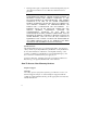
Keywords This section describes valid keywords you can use for each protocol section IP and IP-CALL Sections Keyword Description Operators Value src-addr dst-addr tcp-src-port tcp-dst-addr tcp-one-way udp-src-port udp-dst-addr protocol generic source IP address destination IP address TCP source port # TCP destination port # Limit TCP traffic to one way source port # UDP UDP destination port # protocol-specific field field based on offset, length, mask, value eq/ne eq/ne all all eq/ne all all eq/ne gen
IPX-SAP Section Keyword Description Operators Value network node server service-type socket network address node address server name service type socket number eq/ne eq/ne eq/ne eq/ne all as xx-xx-xx-xx-xx-xx as xx-xx-xx-xx-xx-xx character string (max. 32) 0-ffff in form 0Xxxxx 0-ffff in form 0Xxxxx ATALK and ATALK-CALL Sections Keyword Description Operators Value src-network dst-network src-node dst-node src-socket dst-socket generic source network address destination network add.
8-32 Packet Filters
Chapter 9 Administrative Tools This chapter covers administrative commands that are used for: • Reconfiguring your system • Communicating with a remote or local site • Troubleshooting • Displaying system information • Performing a software download Reconfiguring Your System The commands detailed in this section control configurable aspects of your system.
Command History If you want to customize the history function to change the default (10), use the following command. The limit is 500 commands.
Customizing NETServer Plus Parameters Setting the System With the set system command you can designate a name and location for your LANLinker as well as related contact information and a keyword necessary to make a PPP connection to a remote router over the WAN.
Setting Switch protocol Multipoint Dialing Mode SPID (odd-numbered interface) SPID (even-numbered interface) Directory No. (odd-numbered interface) Directory No.
TELNET Access Port The TELNET Access Port identifies the specific TCP port number that the NETServer Plus should listen to for incoming TELNET sessions. The default is 23, TELNET’s well-known port number. The TELNET Access Port number can range from 1 to 65536. Note that 10000 through 10100 are reserved for an internal filter used for host device port security.
Communicating with Remote and Local Sites Dial and Connect Commands You can dialup a remote or local user with the dial and connect commands and log in to hosts with the rlogin and telnet commands. You can use the hangup and logout commands to clear those lines. Dial Command The dial command makes an immediate connection for a manual dial-out user using the dial-out information in the user's profile. Use the following command: dial Note: The user name must already exist in the system.
Exiting the CLI Bye, Exit, Leave, Quit Commands The bye, exit, leave and quit commands all serve to shut down the CLI but leave the connection open. Logout Command Logout exits the CLI and closes the connection, ending a dial-in user’s or TELNET session. Network Services To use ClearTCP, HTTP or SNMP and to set values associated with them, add each network service and related parameter. TELNET and TFTP are already enabled at startup.
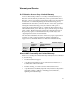
service_name A name you assign to the service being added or edited. Limit of 32 characters. close_active_connections Indicates whether or not to close any active connections when a service is disabled. enabled When you add a network service, it is disabled by default. You can include this parameter while adding the network service to enable it. Be sure to add the enable value after any data value. For example (abbr.): add network serv tel server_t telnetd data auth=off ena yes data Ancillary data.
CONFIGURED NETWORK SERVICES Server Admin Name Type Socket Close Status tftpd TFTPD 69 FALSE ENABLED DATA: dialout DialOut 32773 FALSE DISABLED DATA: auth=off, login_banner= “Welcome to My Net”, login_prompt=“My Session,drop_on_hangup=on telnetd TELNETD 23 FALSE ENABLED DATA: TELNET server TELNETD 99 FALSE DISABLED DATA:” socket Sets the port number the NETServer listens on for network service requests. server_type Type of service being offered (cleartcpd, dialout, httpd, snmpd, telnetd, tftpd).
Note: If you want to allow any system to TFTP into your NETServer, set a TFTP client to 000.000.000.000. Next, from a machine that has access to the same network as the NETServer Plus, use the following TFTP commands to transfer the filter file to the NETServer FLASH memory.
& Optional: After supplying your login name and password, type ] (ctrl ] ) and the telnet: prompt will appear. Closing a Connection The close command shuts down an active TELNET connection. TELNET Control Characters Use the send command to transmit a TELNET control character to a host. After you’ve established a TELNET session, transmit one of the ten available choices, making sure that the characters are all uppercase. See the CLI Reference Guide for your choices.
Troubleshooting Commands Use the commands below to troubleshoot NETServer Plus. Viewing Facility Errors The set facility command allows you to set and view log levels for NETServer’s processes, ensuring that error messages reaching the threshold for that facility will be output to the console port. Note: Although messages are sent to the Console port by default, you can configure a syslog host to receive messages.
Resolving Addresses The arp command performs IP address resolution. Type: arp output NETServer will respond with an IP address (and MAC [Ethernet] address if found on a locally connected network) of the host and will output the data to the FLASH file system. For example: ARP: 172.122.120.118 -> 08:00:09:cc:58:bf Resolving Host Names The resolve name command returns an IP address for a specified host name by sending it to a DNS server for resolution.
For example: ping 199.55.55.55 The command would display the following: 199.55.55.55 is alive If you have the name service DNS, you may see the following: sales_east (199.55.55.55) is alive If the ping is unsuccessful, you’ll see the following: PING: timeout waiting for reply from 199.55.55.55 Using Echo Echo sends a packet to an AppleTalk host (using the AppleTalk Echo Protocol) and the remote station echoes the packet back. You can specify appletalk address (in nn.
They are list switched interfaces, list interfaces and show interface settings, show switched interface. Viewing Netserver Plus System Information You can use the show system command to see what version of NETServer code your NETServer Plus is using. U.S.Robotics Technical Support may require you to furnish this information. The NETServer replies with the firmware revision number, the date and time that this revision was compiled. For example: SYSTEM DESCRIPTION System Descriptor: U.S.
Show Commands You can use show commands to view the NETServer’s current configuration and its routing activity. A few of the show commands used for troubleshooting are covered in this section, including show memory, show connection settings, show connection counters and show accounting information. For a full explanation, see the CLI Reference Guide. Show Memory The show memory command displays the NETServer’s DRAM memory utilization.
Show I-modem parameters The show imodem interface and set imodem interface commands display modem configuration information for the modem specified. To view I-modem switch settings, type: show imodem interface mod:1 settings Note: You can display the same information by invoking the set imodem interface command as follows: set imodem interface mod:1 at_command ati12 The result: USRobotics Total Control MP I-modem with ISDN Switch Settings... Switch Protocol Multipoint Dialing Mode SPID Directory No.
S32=009 S40=000 S48=000 S56=000 S64=000 S33=000 S41=000 S49=016 S57=000 S65=000 S34=000 S42=126 S50=100 S58=000 S66=000 S35=000 S43=200 S51=064 S59=000 S67=016 S36=000 S44=015 S52=005 S60=000 S68=000 S37=000 S45=000 S53=064 S61=000 S69=000 S38=000 S46=255 S54=064 S62=000 S39=000 S47=000 S55=000 S63=000 LAST DIALED #: To use other AT commands, consult the AT manual supplied in your package. Performing a Software Download This section describes how to download a new FLASH file image (.
Figure 1. NETServer 8 Plus I-modem Back Panel V.34 Modem DIP Switches DO NOT change default settings for a software download. Figure 2 shows a row of V.34 modem DIP switches in their factory settings. The defaults reflect typical system requirements such as: Result Codes displayed, AT commands enabled and Remain Connected on Escaped Code. If you think the factory settings need to be changed, see the table in Appendix C: LEDs and DIP Switches. Figure 2. V.
ON 1 2 3 4 OFF Figure 3. I-modem DIP Switches (factory defaults) Switch 1 2 3-4 Function Power-on/Reset Load Configuration Defaults OFF Load from nonvolatile memory (NVRAM) ON Load factory settings from ROM AT Command Set Recognition OFF Command recognition disabled (Dumb mode). Not a valid setting when the I-modems are used with NETServer. ON Enabledcommand set recognized (Smart mode) Reserved These switches are reserved for use by U.S. Robotics. Please do not change their settings.
Switch 1-2 Function Console Port Baud Rate If DIP switch 3 is on (down), these two switches set the baud rate for the console port on the back of the unit. Note that these switches control the external CONSOLE port only. If DIP switch 3 is off (up), switch 1 and 2 have no effect. To match the default baud rate setting (38400 Bps) in the PCSDL program, set switch 1 to ON and switch 2 to OFF. 19200 9600 1 2 1 2 1 2 1 2 38400 57600 Figure 5.
WARNING! This switch erases everything. After you use it, you must start over from scratch. We recommend you save your present FLASH files to a PC in case you want to reinstall the old image later. 5-10 Reserved These switches are reserved for use by U.S. Robotics. Please do not change their settings. Installation Begin the software download process by following the steps below. The section describes how to download the PCSDL files. IMPORTANT: Be sure your NETServer is turned OFF before you begin.
Note: The SDL batch file will use the Com 1 port on your PC to download to the FLASH file system. This default can be modified to Com 2 by changing the first x value. You may also change the baud rate from the default of 38400 bps. pcsdl -px -r%BAUDERATE% -vSD”SDL version” -vNA”Image version” -nSDtr -nNApn For example: pcsdl -p2 -r38400 -vNA9.9.9 -vNA 4.0.0 -nSDtr -nNApn 8 If your settings are correct, type: sdl.bat 9 When the application begins loading, power on your NETServer.
Network Products Corporation (Pasadena, CA) All rights reserved. AppleTalk-compatible networking software is Copyright 19931995, Quiotix Corporation (Menlo Park, CA) All rights reserved. TCP/IP networking software is Copyright 1988-1995, Epilogue Corporation, Albuquerque NM, All rights reserved. IP routing software is Copyright 1993-1995, RainbowBridge Communication. Inc. Rockville MD, All rights reserved. IPX networking software is Copyright 1994-1995, RouterWare Inc.
Appendix A Notices & Technical Specifications This chapter describes: • Notices • Hardware specifications • Environmental Specifications • Power Specifications • External Serial Port Specifications • Ethernet Interface Specifications • Token Ring Interface Specifications • Modem Interface Specifications • System Standards and Specifications • Software Specifications Notices: United States FCC Part 15 Compliance Statement This equipment has been tested and found to comply with the limits
This equipment generates, uses and can radiate radio frequency energy and, if not installed and used in accordance with the instructions, may cause harmful interference to radio communications. However, there is no guarantee that interference will not occur in a particular installation.
BRI U Model: FCC Part 68 Compliance Statement This equipment complies with Part 68 of the FCC rules concerning: • FCC Registration Number: labeled on the product • Facility Interface Code: 02IS5 • Service Order Code: 6.0Y • USOC Jack: RJ49C • REN: Not Applicable BRI S/T Model: FCC Part 68 Compliance Statement This equipment complies with Part 68 of the FCC rules concerning: • FCC Registration Number: labeled on the product • Facility Interface Code: 02IS5 • Service Order Code: 6.
FCC compliant telephone cords and modular plugs are provided with this equipment. This equipment is designed to be connected to the telephone network or premises wiring using a compatible modular jack which is Part 68 compliant. See installation instructions for details. The NETServer Plus cannot be used on public coin phone service provided by the telephone company. Connection to party line service is subject to state tariffs.
Canadian Installations The Industry Canada (formerly Canadian Department of Communications) label identifies certified equipment. Certification means that equipment meets certain telecommunications network protective, operational, and safety requirements. The department does not guarantee the equipment will operate to the purchaser’s satisfaction. Before installing this equipment, be sure a connection to a local telecommunications company is permissible. Install equipment using an acceptable method.
Environmental Specifications Shipping and storage Temperature: -25° to +75° Celsius, -13° to +167° Fahrenheit Relative Humidity: 0 to 100% noncondensing Operating Temperature: 0° to +40° Celsius, 32° to +104° Fahrenheit Relative Humidity: 0 to 95% noncondensing Power Specifications Power requirements AC PSU: Nominal 120V (90-264 VAC) @47-63 Hz Maximum output power 125 watts Maximum input power +5 V 18 A +12 V 1.9 A -12 V 1A 160 watts 1.3 A Typical input power MTBF A-6 8 port 57 watts 0.
External Serial Port (Console) Specifications Pinouts 8-Position Modular Jack Circuit Function Direction 1 2 3 4 5 6 7 8 CC CF CD AB BB BA CB CA Data Set Ready Carrier Detect Data Terminal Ready Signal Ground Receive Data Transmit Data Clear to Send Request to Send Inbound Inbound Outbound Inbound Outbound Inbound Outbound Electrical Specifications Specification Description Connectors RS-232, 8-position modular jack (Stewart 88-360808 or equivalent) DB-25 Amp 748677-1 or equivalent Configur
Wire type Belden 9538 or equivalent, 8 conductor, shielded Maximum cable distance 50 feet, 15 meters Cabling 8-position modular jack to DB-25 (IBM AT pin-out) Nominal Direct Current Resistance Center conductor 24 gage (7 strands 32 gage) .61 millimeter diameter 23.7 ohms/1000 feet 77.8 ohms/kilometer Shield 15.5 ohms/1000 feet 50.9 ohms/kilometer Nominal outside diameter .265 inch; 6.
Cable Specifications Data Transfer Rate 10 Mbps Accessing Scheme CSMA/CD (Carrier Sense Multiple Access with Collision Detection) Topology Star Wired Hub (using multiport repeater) Maximum Nodes Limited only by repeater used Transmission Medium Unshielded Twisted Pair Network Lobe Distance 100 meters (328 ft.) suggested max. Longer cabling can be used at the expense of reduced receiver squelch levels. Connector 8-position modular jack, Stewart 88360808 or equivalent Wire Type .
10Base-2 (BNC) Pin Function Center Signal Shield Isolated GND Cable Specifications A-10 Data Transfer Rate 10 Mbps Accessing Scheme CSMA/CD (Carrier Sense Multiple Access with Collision Detection) Topology Bus Maximum Nodes 30 Trans. Medium Coaxial cable Network Lobe Dist. Minimum separation of .5 meters Connector Type BNC “T” Wire Type Coaxial Center conductor .89 ± .05 mm diameter stranded, tinned copper Shield 2.95 ± .
Modem Interface Specifications Your modem uses multiple standard modulation protocols and is also compatible with many nonstandard schemes. ITU-T V.34 28.8K, 26.4K, 24K, 21.6K, 19.2K, 16.8K, 14.4K, 12K, 9600, 7200, 4800, and 2400 bps asynchronous Trellis Coded Modulation (TCM) V.Fast Class (V.FC) 28.8K, 26.4K, 24K, 21.6K, 19.2K, 16.8K, 14.4K bps asynchronous Trellis Coded Modulation (TCM) terbo 21.6K, 19.2K, 16.8K, 14.4K. 12K, 9600, 7200 bps asynchronous, 19.2K, 16.8K, 14.4K.
• Bell 212A, 1200 bps, asynchronous, Differential Phase Shift Keying (DPSK) • Bell 103, 300 bps, asynchronous, Frequency Shift Keying (FSK) • ITU-T V.21, 300 bps, asynchronous, Frequency Shift Keying (FSK) System Standards and Specifications Error Control Standards • ITU-T V.42 error control protocol at 14.4K, 12K, 9600, 7200, 4800 bps (V.32 bis mode) and at 2400/1200 bps • Microcom Networking Protocol (MNP) error control protocol, Levels 2-4 at 14.4K, 12K, 9600, 7200, 4800 bps (V.
Fax Standards A Total Control MP modem provides Group III-compatibility when combined with Class 1 or Class 2.0 fax software. In addition, the modem adheres to the following standards. TIA/EIA-578 Service Class 1 Asynchronous Facsimile DCE Control Standard TIA/EIA-592 Service Class 2.0 Asynchronous Facsimile DCE Control Standard ITU-T V.17 14.4K/12K bps ITU-T V.29 9600/7200 bps ITU-T V.27 ter 4800/2400 bps ITU-T V.21 300 bps Serial Port Rates 115.2K, 57.6K, 38.4K, 19.
Data Format Binary, serial; defaults to 8-bit word length, no parity, and 1 stop bit Word Length Parity (1 Bit) Stop Bits 7 Even, Odd Mark, Space 1 7 None 2 8 None 1 Flow Control Buffer Capacity Transmit Buffer Error control: 3.25k bytes Non-Error control: 1.
Failed Call Time-out 60-sec. default, programmable 2-255 sec. Answer Tone Time-out 60 sec. Fax Service Class 1 Commands +FCLASS=n (0,1, 2.0) Class identification and control +FTS=n (0,255) Stop transmission and pause, 10ms.
FAX Service Class 2 Commands Class 2.0 fax commands are too numerous to be listed here. For information on Class 2.0 technical specifications, contact Global Engineering Documents, at 1-800-854-7179. The document that covers this information is: ANSI/EIA/TIA-592-1993 (EIA-592) Asynchronous Facsimile DCE Control Standard May, 1993 U.S. Robotics also implements the following optional Class 2.
Transmitter Carrier Frequencies Originate Mode: 1800 Hz Answer Mode: 1800 Hz Originate Mode: 1829 Hz Answer Mode: 1829 Hz Originate Mode: 1867 Hz Answer Mode: 1867 Hz Originate Mode: 1920 Hz Answer Mode: 1920 Hz Originate Mode: 1959 Hz Answer Mode: 1959 Hz Originate Mode: 2000 Hz Answer Mode: 2000 Hz V.Fast Class Originate Mode: 1800 Hz Answer Mode: 1800 Hz Originate Mode: 1875 Hz Answer Mode: 1875 Hz Originate Mode: 1920 Hz Answer Mode: 1920 Hz USR-V.32 terbo/V.32 bis/V.
bis, V.
Originate Mode: 2000 Hz Answer Mode: 2000 Hz V.Fast Class Originate Mode: 1800 Hz Answer Mode: 1800 Hz Originate Mode: 1875 Hz Answer Mode: 1875 Hz Originate Mode: 1920 Hz Answer Mode: 1920 Hz USR-V.32 terbo/V.32 bis/V.32 Originate Mode: 1800 Hz Answer Mode: 1800 Hz USR-V.32 terbo/V.32 bis/V.32 Originate Mode: 1800 Hz Answer Mode: 1800 Hz Originate Mode: Mark 1300 Hz Space 2100 Hz Answer Mode: Mark 390 Hz Space 450 Hz bis, V.
Bell 103 Originate Mode: Mark 2225 Hz Space 2025 Hz Answer Mode: Mark 1270 Hz Space 1070 Hz Originate Mode: Mark 1650 Hz Space 1850 Hz Answer Mode: Mark 980 Hz Space 1180 Hz Receive Sensitivity - 44 dBm + 2 dBm Transmit Level - 9 dBm maximum Transmitter Frequency Tolerance .
Software Specifications Routing Support • Transparent On-Demand, manual, timed, continuous and Bandwidth on demand routing • IP, IPX and AppleTalk protocol routing • Inverse multiplexing with programmable load balancing • Host, subnet, and network routes supported • Selective default routing • Continuous connection (automatic retries after connection loss) Administration • Local FLASH ROM for booting & configuration storage • Support for Domain Name Service (DNS) • Call activity logging • SNMP management
Filtering & Security • IP, IPX (RIP and SAP), AppleTalk, IP RIP, and source/destination filtering • Set inbound and outbound Packet Filtering independently • Compatible with RADIUS authentication servers • IP and IPX address pools PPP Specific Features • Address and control field compression • Protocol field compression • PAP and CHAP authentication protocols • Magic number loopback detection • Maximum receive unit negotiation • Async control character map negotiation • IP Address negotiation and assignmen
Client Dial-up Support • ARAP, SLIP, CSLIP, and PPP with automatic PPP detection • Telnet and Rlogin • Remote ODI client drivers • Dynamic address assignment per call • Rlogin SLIP and PPP Client Software Support • We support clients which adhere to PPP, IPCP, IPXCP and ATCP RFCs.
A-24 Notices & Technical Specifications
Appendix B Addressing Schemes This appendix contains a brief introduction to the IP and IPX addressing schemes for administrators that are new to either one or both. The following topics are discussed: • IPX addressing basics • IP addressing basics • Supernetting IPX Addressing Basics Unlike TCP/IP, Novell’s IPX protocol uses two separate address fields for each network interface: a 4 octet (4 byte) network number and a 6 octet node address.
IP Addressing Basics There are three address classes in IP, ranging with addresses ranges as follows: Class A - 0-127; Class B - 128 - 191; and Class C - 192 - xxx. IP addresses are 32 bits long and generally written in what is called dotted decimal notation: four decimal values separated by periods. For example, 192.77.203.5. These 32 bits are structured very differently from IPX addresses, in which you always have an 8 hex digit network number followed by a 12 hex digit node address.
Subnetting A large IP network can be subdivided into smaller subnetworks. This is done using a device called the subnet mask (in this text, often called netmask), which tells a routing device how to further subdivide the Host ID portion of an IP address. A subnet mask is a 32 bit value which is written in dotted decimal notation. It contains a number of bits set to 1 (indicating the network portion of an address) followed by a number of bits set to 0 (indicating the host portion of an address).
Subnets of Class C networks Since Class C networks are by far the most common, we will take a closer look at subnetting in a Class C network. The following table is a listing of all possible values for the last octet (byte) in a Class C subnet mask.
Reserved Addresses In most IP machines, setting all the bits in the host portion of an IP address to 1 indicates a broadcast to all nodes on the network. In the Class B network described above, an address of 128.5.255.255 is a network broadcast address meaning the packet is destined for all nodes on the entire Class B network. 128.5.63.255 would be a broadcast address indicating that the packet is destined for all nodes on subnet 63.
Supernetting (Advanced TCP/IP) Because Class B Internet addresses are in short supply, larger networks are now usually granted a contiguous block of several Class C addresses. Unfortunately, this creates very large routing tables since multiple Class C routes have to be defined for each network containing more than 254 nodes. Larger routing tables mean more work for the routers and, therefore, poorer performance.
Supernetting, or CIDR (Classless InterDomain Routing) is a technique that allows each of these larger networks to be represented by a single routing table entry, as shown in Figure 3 below. Figure 3. Sample Supernetting - CIDR - Topology To do this, supernet addressing does something very different from traditional TCP/IP routing (which allows only one netmask per network). In supernet routing, each supernet can be assigned its own netmask.
This example creates supernets composed of fewer than 254 Class C networks. So, their netmasks are actually splitting up the third octet in their IP addresses. See Figure 4 below. Figure 4. Sample CIDR Netmask Notice that the number of zero bits in the third octet actually dictates the number of Class C networks in the supernet. Each zero bit makes the supernet twice as large. So, a supernet composed of 8 Class C networks would actually have 3 zeroes 3 (8 = 2 ).
Step 2 - Select a range of addresses for each supernet The range of addresses in a supernet must fit exactly into a space that can be described by its netmask. This means that the zero bits in the netmask must also appear in the first address of the supernet block. For this to be true, the third octet in the address must be an even multiple of the same power of 2 used to form the netmask.
Supernet Example The four networks in the example below are all connected to the same Internet service provider (ISP). The ISP has decided to use supernetting to reduce the size of his routing tables and improve throughput. See Figure 6 below. Figure 6. Sample Supernets • Supernets 1 and 2 each require four Class C networks, so 2 they require a netmask with 2 zero bits (4 = 2 ) in the third octet. This yields a netmask of 255.255.252.0. • Supernet 3 requires 7 Class C address spaces.
Supernet 3 requires an even multiple of 8. It also can begin on the next available address. Since supernet 4 can fit entirely in a single Class C address space, it can use supernet 3’s surplus space. It is therefore given the last Class C address space in Supernet 3’s territory, effectively reducing supernet 3 to only the 7 class C networks it needs. Supernetting and the NETServer In order to define a supernet on the NETServer, you must add the network address and its netmask.
IP Subnet Mask Address Table Subnet masking is used to expand the number of networks due to the 32-bit limitation of IP’s address field. When assigned an address by the NIC, the address can be further broken down to expand the single net number to many more by using host bits. Subnet Bits Bit Positions Decimal Mask Class A 0nnnnnnn.hhhhhhhh.hhhhhhhh.hhhhhhhh 10nnnnnn.nnnnnnnn.hhhhhhhh.hhhhhhhh 10nnnnnn.nnnnnnnn.sshhhhhh.hhhhhhhh 10nnnnnn.nnnnnnnn.ssshhhhh.hhhhhhhh 10nnnnnn.nnnnnnnn.sssshhhh.
Appendix C LEDs and DIP Switches LED Overview There are two rows of LEDs on the NETServer/8, three rows of LEDs on the NETServer 16. • In the 8-port NETServer, the top row of LEDs contains the status indicators for all eight V.34 or I-modems. • In the 16-port NETServer, the top two rows are indicators for the modems. • The bottom row of LEDs on all units contains indicators for the NETServer control circuitry and network interface. Figure 1 below displays LEDs on NETServer Plus/16.
Run/Fail LED The Run/Fail LED next to the row of V.34 or I-modem indicators correspond to the entire row of modems. The LED behaves in the following manner. Color Meaning Off Green Red Power off Power on Critical failure During startup tests, this LED cycles through several colors. The lower Run/Fail LED indicates the status of the NETServer hardware.
Modem Indicators Each V.34 or I-modem indicator (1 - 16) shows the status of one modem. The number for each modem corresponds to its port number (mod:1, mod:2, etc.).
NETServer Indicators Flash ROM LED Lights when flash memory is being updated. Color Meaning Red Startup (during POST) Green Erasing flash memory Amber Programming flash memory Off Normal LAN TX LED Indicates packets are being transmitted through the LAN (Ethernet) interface.
LAN STATUS LED Indicates the status of the LAN (Ethernet) interface Color Ethernet Red Interface failure Green Link present MGT LED Indicates activity at the external console port. It flashes green when characters are transmitted or received through the external serial port. DIP Switches There are two rows of DIP switches on the NETServer/8. The MODEM CONFIGURATION (unnamed for I-modems) DIPs control I-modem or V.34 modems.
These switch settings are defaults only and remain in effect only until configuration is changed using AT commands. Figures 3 below and 4 on page C-8 depict a row of V.34 and Imodem DIP switches in their factory default settings. Defaults are the recommended settings with the NETServer hardware. Note that these switches are functionally the same as the DIP switches on a U.S. Robotics Courier I-modem. ON 1 3 2 4 5 6 7 8 9 10 OFF Figure 3. V.34 DIP Switches V.
Switch 4 Function Disable Command Mode Local Echo OFF Keyboard commands displayed ON 5 Echo suppressed Disable Auto Answer OFF Modem answers on first ring ON 6 Auto answer disabled Carrier Detect Operations OFF Normal CD operations. A modem sends the carrier detect signal when it connects with another modem, and drops the carrier detect on disconnect.
I-modem DIP Switches There are 4 I-modem DIP Switches. See Figure 4 below. ON 1 2 3 4 OFF Figure 4. I-modem DIP Switches (factory defaults) Switch Function 1 Power-on/Reset Load Configuration Defaults 2 OFF Load from nonvolatile memory (NVRAM) ON Load factory settings from read only memory (ROM) AT Command Set Recognition 3-4 OFF Command recognition disabled (Dumb mode). Not a valid setting when the I-modems are used with NETServer.
NETServer CONFIGURATION DIP Switches The NETServer CONFIGURATION DIP Switches control the NETServer hardware. See Figure 5 below. ON 1 2 3 4 5 6 7 8 9 OFF 10 Figure 5. NETServer CONFIGURATION DIP Switches (factory defaults) Switch Function 1-2 Console Port Baud Rate If DIP switch 3 is on (down), these two switches set the baud rate for the console port on the back of the unit. Note that these switches control the external CONSOLE port only.
Switch Function 4 Erase/Reinitialize Flash Configuration If this switch is on when the NETServer is booted, the configuration data saved in flash memory is erased. When the machine is finished rebooting, you must set this switch back to the off position before you will be allowed to continue configuring the NETServer. WARNING! This switch erases everything. After you use it, you must start over from scratch. 5-10 Reserved These switches are reserved for use by U.S. Robotics.
Appendix D Event Messages This appendix includes information about the NETServer event message facility that logs event messages to a syslog host, console, or local flash file. This appendix provides some event message examples that include descriptions of the message and suggested action you can take to correct problems. Event Logging The NETServer event logging system logs important information about NETServer processes to a number of logging sinks.
Important: You must have the NETServer entered in the \etc\hosts file of the UNIX server that is running Syslog. Without this, you will be unable to use Syslog network accounting with the NETServer. Console Event Logging Event messages are automatically displayed on a local console. Local Flash File Event Logging The NETServer event logging system maintains a file - logfile.local - in the flash file system that contains a circular buffer of the last 20 event messages generated by the NETServer.
• Unusual - An event that should not happen in the normal operation, but from which the system should be able to recover • Common - A normal event that does not happen frequently • Verbose - A normal occurrence that happens frequently • Debug - For debugging purposes only You can configure whether event messages are sent to a logging sink according to the level of the message.
can be one of the following: Critical a serious system error that may effect system integrity. Unusual an abnormal event from which the system should be able to recover. Common a regular but infrequent event Verbose a regular periodic event Debug for debugging only For example, to define a syslog host that logs Common, Unusual, and Critical events, use the following command: add syslog 191.54.42.
Event Message Examples The NETServer is capable of delivering hundreds of event messages, from common events to critical events. This section attempts to describe some representative event messages that are generated by NETServer facilities. Each event message is categorized by the facility by which it is generated. The message description includes information about the meaning of the message, and if necessary, any corrective action you can take.
"ip_addr_pool_init: bad address pool range (%lx), the value must be between 1 and 254. \n" Meaning: The administrator tried to specify the size of the IP address pool using a value that is either too big (greater than 254) or too small Action: Specify a pool size that is within this range using the set ip system pool_members command "ip_send_common: on demand route, X, input queue overflow.
"proxy_arp_insert: no common network address found for remote ip address X" Meaning: A network user is connecting to the system using an IP address that is not on the same IP subnetwork as the network defined for the system's LAN interface. Therefore, no proxy ARPing will be performed for this user. Action: Informational message. No action required "IP routes created for ondemand users cannot be deleted this way. Disable the user to delete the route.
"ip_fwd_add_ondemand: ondemand IP network address (X) conflicts with an IP network that already exists.\n" Meaning: The administrator has defined an on-demand user whose remote IP address is already being used by an existing IP network Action: Change the on-demand user's remote IP address to one that does not conflict with any existing networks. Tip: Use the list ip net command to view the existing IP network addresses currently in use.
If the IPX network address for the WAN link is configured based on the IPX address, modify the address pool to exclude that specific IPX address "Failed to fetch user info %d, status = %d/n" Meaning: The IPX process tried to get user-specific information but failed Action: The user may be disabled. Check the state of the user using the show user command. "Call initiate failed for an unknown user %x/n" Meaning: The IPX process tried to make a dial-out connection for an on-demand user.
"CIP: The modem group %s already exists /n" Meaning: The administrator tried to configure a modem group, but the modem group already exists Action: Choose another modem group name User Manager Messages "AUTH: Unable to authenticate if both authentication IP's are set to 0" Meaning: The user may not be defined locally, remote authentication is not enabled, or a remote authentication IP address is not configured Action: Define the user locally or configure a RADIUS server IP address "AUTH: Unable to
Action: A protocol section must either contain at least one rule, or the section must be commented out for the syntax to be valid "FM: In filter file , previously defined section " Meaning: There are two protocol sections that use the same name, for example, you defined two IP protocol sections in the filter file Action: Delete on of the duplicate protocol sections "FM: In filter file , ambiguous first line" Meaning: The filter file does not contain the required f
"The configuration file is corrupt. Status ." Meaning: The Configuration file has been corrupted. It will be renamed to .bad Action: Keep a copy of the .bad file. If the file was uploaded to using TFTP, upload the file again making sure the TFTP transfer mode is set to octet "Could not create a list for CFM Control Structures. Status: .
IPX/IP Dial-out Process Messages "INIT: Could not allocate a private data area. Status: ." Meaning: The dialout process could not allocate enough memory for its data. The dialout process will not be started Action: Free some memory, for example, delete some users. Once some memory has been freed, save the configuration and reboot the system "Could not register socket with the IPX forwarder. Status: ().
"Could not set the IPX ACS timer. Status: (). The IPX Dial-out service will be automatically disabled." Meaning: The dialout process could not start its service timer. This timer is required for normal operation. The dialout network service will not be enabled Action: A system error occurred. If re-enabling the dialout network service fails, reboot the system "There are no interfaces assigned to the Dial-out process' modem groups.
Appendix E RADIUS Authentication and Accounting Remote Authentication Dial In User Service (RADIUS) is a distributed security system that secures remote access to networks and network services against unauthorized access.
RADIUS Accounting The RADIUS accounting server can perform session accounting for the NETServer. Session accounting information includes date and time, user information, service type, login host, and login service. When RADIUS accounting is enabled, the NETServer forwards an accounting record for each session to be stored on the accounting server. Note: The NETServer syslog facility also performs local session accounting. For more information about syslog accounting, refer to Appendix D, Event Messages.
If you enable: • Local authentication only - the NETServer grants or denies access based on the information in the local user table only. • RADIUS authentication only - the NETServer sends a request to the RADIUS server and grants or denies access based on the response. • Both local and RADIUS authentication - the NETServer first checks the local user table. If the user is defined in the local user table, the NETServer grants or denies the user access based on the information in the table.
RADIUS Security Server User Table Entries RADIUS user table entries are stored in the RADIUS security server database. A user table entry must contain required parameters such as the user's name, password, and service type. In addition, you can enter optional parameters such as protocol, address, and session parameters. This section briefly describes how to format the entries commonly used with the NETServer in the RADIUS database.
User-Name The user name the user must enter when logging onto the network via the NETServer. Values ASCII string (maximum 32 characters) Default None Use the following command to set this parameter locally: add user password Note: You must specify the user's password when adding the user. User-Password The password the user must enter when login onto the network via the NETServer. If your RADIUS server supports UNIX, the password can also be a quoted value of UNIX.
Optional Parameters The following sections describe optional user parameters that you can define in the RADIUS authentication server database. Each parameter description also includes the corresponding command you can use to define the same information in the local NETServer User Table. Note: For detailed information about local user parameters using commands, refer to the appropriate chapter in this guide for the type of user you are configuration. You can also refer to the CLI Reference Guide.
Login-User The CLI also calls this a Login user. Once the user name and password are authenticated, this user is connected via a login service to the host or network specified in RADIUS or in the local user table. At a minimum, a Login-User entry must contain: • User-Name • User-Password • Service-Type For example: annab User-Password=“dkt902d” Service-Type=Login-User Dialback-Login-User The CLI defines this user type as two separate user types: Login and Callback.
Framed-User The CLI calls this a Network user. Once the user ID and password are authenticated, users are connected to the network using the network service (PPP or SLIP) specified in RADIUS or in the local user table. Note: RADIUS does not support ARAP users. You must authenticate and define configuration parameters for these users in the local user table.
For example: harryk Password=“flipper”, Service-type=Framed-User, Framed-Protocol=PPP Dialback-No=“15088470203” Outbound-User The NETServer defines this user type as a Dial-Out user. An outbound user is a user on the LAN who is using the shared modems to dial out. A Outbound-User entry must contain: • User-Name • User-Password • Service-Type Administrative-User The NETServer defines this user type a Manage user. The administrative user has management access capabilities for the NETServer.
Use the following command to set this parameter locally: set network user network_service [ARAP | PPP | SLIP] Framed-IP-Address Specifies the IP address that is assigned to the user for the duration of the connection. If the NETServer is configured to use Assigned Addresses, this field is not applicable. The NETServer will assign the user a temporary IP address from the Assigned Address pool for the duration of the connection. Values IP address Default 0.0.0.0 The address 255.255.255.
Note: If you do not enter a mask value following the IP address, the NETServer automatically sets the netmask to 255.255.255.255. Framed-Routing Determines whether the NETServer permits Routing Information Protocol (RIP) packets to be sent to or from the remote user. Note: This parameter only applies to IP RIP v1 in RADIUS. The NETServer software supports both IP RIP v1 and IP RIP v2.
The syntax for specifying the for incoming and/or outgoing packets is: Filter_ID= input filter filename / output filter filename For example, if you want to specify a filter that is applied to incoming packets only (input filter): Filter_ID=pktfilter.fil To specify a filter that is applied outbound packets only (output filter), place a slash (/) before the output filter filename. For example: Filter_ID=/my_filter.
The address 255.255.255.255 causes the user to be prompted, while the address 0.0.0.0 causes the server to pick a connection host from the default host table. You can use the following CLI command to determine whether a user's client IP address is negotiated, assigned, or specified by the user: set login user host_type [prompt | select | specified] Note: If you set the user's host type to specified, you must also specify the host ip address.
Reply-Message Indicates text which may be displayed to the user. Values ASCII string (maximum 253 characters) Default NULL Use the following command to set this parameter locally: set user message <"message_text"> Expiration Specifies the date on which the user’s password expires, and must be enclosed in quotes. For example, “December 1, 1998”.
Note: If the connection is configured to use the assigned addresses, or if the address is negotiated, and you set the destination to 0.0.0.0, the NETServer will “learn” the gateway to reach the host or network. Values ASCII string (maximum 253 characters) Default NULL Use the following command to set this parameter locally: add framed_route user ip_route gateway metric Framed-IPX-Network Indicates the IPX network number configured for the user.
Idle-Timeout Sets the maximum time (in seconds) that a connection can be idle before the session is automatically terminated. Values Decimal value Default 300 Use the following command to set this parameter locally: set user idle_timeout NETServer-Specific Parameters This section describes the NETServer-specific authentication parameters that you can enter for a user in the RADIUS database. These parameters directly correspond to parameters supported by the NETServer software.
Channel-Expansion Indicates the channel expansion percentage for a LAN-to-LAN connection. When the amount of usage of the first channel exceeds this percentage, PPP will add the second channel. Values percentage ranging from 1-100 Default 60 Use the following command to set this parameter locally: set network user ppp channel_expansion Channel-Decrement Indicates the channel decrement percentage for a LAN-to-LAN connection.
Expansion-Algorithm Specifies which type of expansion algorithm should be used to decompress incoming PPP data. Values Constant Linear Default Linear Use the following command to set this parameter locally: set network user ppp expansion_algorithm [CONSTANT | LINEAR] Receive-Acc-Map Determines whether the NETServer uses the asynchronous control character map to filter incoming data.
Compression-Reset-Mode Determines how often PPP should examine packets to decide when to re-negotiate the optimum compression algorithm. Values auto reset every packet reset on error Default auto Use the following command to set this parameter locally: set network user ppp reset_mode_compression [auto | every_error | every_packet] Min-Compression-Size Specifies the minimum size at which PPP compresses a packet. Data packets smaller than this value are not compressed.
IPX Indicates whether IPX is enabled for the user. Values enabled disabled Default enabled Use the following command to set this parameter locally: set network user ipx [enable | disable] Spoofing Indicates whether protocol spoofing is enabled for the user. Spoofing reduces WAN traffic between routers by intercepting queries from a server to a client and replying to that server.
Start-Time Indicates the time that the NETServer starts this connection. Values RoboTime Default 0 Use the following command to set this parameter locally: set dial_out user site start_time
Configuring RADIUS from the CLI This section provides descriptions of CLI commands used to manage the RADIUS security server authentication process. Topics include: • Configuring RADIUS authentication settings • Enabling and disabling authentication Configuring RADIUS Authentication Settings This section assumes that RADIUS security server is already up and running on a workstation on your network.
The RADIUS server(s) must be set to the same encryption key or secret. The encryption key is entered into the "clients" file for the RADIUS server. The encryption key can be up to 15 characters long. Refer to your RADIUS documentation for more information. set authentication primary_secret 4. Optional. Set the secondary encryption key or secret. set authentication secondary_secret 5. Set the number of retransmissions.
Configuring RADIUS Accounting Settings The NETServer sends frames to the RADIUS accounting server that enable RADIUS to perform accounting functions. The RADIUS accounting server uses the same basic protocol as the RADIUS security server. Both servers may run on the same host, but you may choose a different host to provide each function. The accounting server creates a separate account file for each NETServer under the following directory.
If your network has more than one RADIUS accounting server, indicate which one will be considered the secondary server. If for some reason the primary server is unavailable, the NETServer will check with the secondary server. set accounting secondary_server 3.
Note: Syslog accounting is always enabled as long as a syslog sink is defined. For more information about Syslog accounting, refer to Appendix D, Event Messages RADIUS Accounting Examples Below of a few examples of RADIUS accounting output. The first example is for a login user who has just begun a session.
When the framed user ends the session, a record like the one below is sent to the accounting server: Thurs Jan 16 16:25:57 1995 Acct-Session-Id=“06000004” User-Name=harryk Client-Id=201.123.234.79 Client-Id-Port=5 Acct-Status-Type=Stop Acct-Session-Time=664 Acct-Authentic=Local User-Service-Type=Framed-User Framed-Protocol=SLIP Framed-Address=122.132.124.152 Framed-Netmask=255.255.124.
E-28 RADIUS Authentication and Accounting
Index A D Accounting server RADIUS ........................ E-27–E-30 Syslog.......................... Appendix D ADD command .............................. 3-3 Help........................................... 3-3 Application set up Network dial in access..... Chapter 5 Terminal server................ Chapter 4 Authentication CHAP ................... 7-10–7-11, E-24 PAP ......................................... 7-10 Passwords.................................. E-3 Default gateway....................
Default gateway....................... 2-14 System name............................ 2-11 Group number (location) ............. 7-16 MTU ........................................7-14 On-demand dialing...................7-17 RIP messaging .........................7-18 Login user.............................Chapter 4 in RADIUS ............................... E-7 H HELP command............................. 3-3 Hosts table Overview ................................... 3-5 I Input filter...............
P Package, what’s included............... 2-3 Packet filters ........................ Chapter 8 Deleting filters......................... 8-20 Information sources................... 8-3 IPX rules .... 8-26–8-28, 8-26–8-28, ................................... 8-26–8-28 Overview ................................... 3-7 TCP parameters ....................... 8-23 Types of filters........................... 8-2 UDP parameters ...................... 8-23 Uses of.......................................
TCP/IP ........................See TCP and IP Telnet Administrative session............... 9-3 Filtering ................................... 8-24 Login port service......................D-5 Login user service .....4-6, 4-7, 5-10 Overview ................................... 3-4 Telnet access port .......................... 9-3 Terminal server, using NETServer a Chapter 4 Overview ................................... 1-7 Terminal setup........................... 4-2 Troubleshooting commands..
Index 5