
User`s guide

68 56K Message Modem
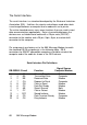
The Serial Interface
The serial interface is a standard developed by the Electronic Industries
Association (EIA). It defines the signals and voltages used when data
is exchanged between a computer and a modem or serial printer.
The entire standard covers many more functions than are used in most
data communications applications. Data is transmitted between the
devices over a shielded serial cable with a 25-pin male (DB-25P)
connector to the modem and a 25-pin, 9-pin, 8-pin, or custom-built
connector to the computer.
Pin assignments are factory-set in the 56K Message Modem to match
the standard DB-25 assignments in the following table. DB-9
connectors for IBM/AT-compatible computers should be wired at the
computer end of the cable as shown in the DB-9 column.
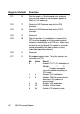
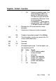
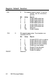
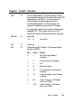
Serial Interface Pin Definitions
Signal Source
DB-25DB-9 Circuit Function Computer/Modem
1 — AA Chassis Ground Both
2 3 BA Transmitted Data Computer
3 2 BB Received Data Modem
4 7 CA Request to Send Computer
5 8 CB Clear to Send Modem
6 6 CC Data Set Ready Modem
7 5 AB Signal Ground Both
8 1 CF Carrier Detect Modem
12 — SCF Speed Indicate Modem
20 4 CD Data Terminal Ready Computer
22 9 CE Ring Indicate Modem