3Com U.S.
This manual covers installation and operating instructions for the following modem: • 3Com U.S. Robotics 56K Message Modem external modem IMPORTANT MESSAGE: In accordance with the ITU-I standard for 56K transmissions, this modem is capable of 56Kbps downloads. However, the download speeds you experience may be lower due to varying line conditions and other factors. Uploads from users to server equipment travel at speeds up to 31.2 Kbps. An analogue phone line compatible with the ITU-T 56K standard (V.
Table of Contents WELCOME TO 56K* INFORMATION ACCESS..................................1 PRODUCT FEATURES........................................................................2 FAX STANDARDS .................................................................................2 SUMMARY OF FEATURES .................................................................4 REMOTE VOICE RETRIEVAL ..................................................................
SECTION C : GLOSSARY ....................................................................35 SECTION D : TECHNICAL QUICK REFERENCE........................................45 Basic Data Commands ................................................................48 S-Registers..................................................................................58 The Serial Interface......................................................................68 SECTION E : CE COMPLIANCE ......................................
Welcome to 56K* Information Access The International Telecommunications Union (ITU) decides the technical protocols communications devices must use to interoperate with each other. Modems that comply with ITU standards can “talk to” other standards-compliant modems and fax machines worldwide. The ITU has decided on a worldwide 56K standard technology. So, now with a U.S. Robotics modem you can get all the Internet you want from any service provider who offers the V.
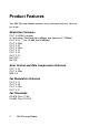
Product Features Your 56K Message Modem provides many advanced features. Here are just a few : Modulation Schemes ITU-T V.90 56K standard x2 Technology (Download up to 56kbps, and Upload at 31,200bps) ITU-T V.34 (Inc. 33,600 and 28,800bps) ITU-T V.32bis ITU-T V.32 ITU-T V.22bis ITU-T V.22 ITU-T V.23 ITU-T V.21 Bell 212A Bell 103 Error Control and Data Compression Schemes ITU-T V.42 ITU-T V.42bis MNP 2-5 Fax Modulation Schemes ITU-T V.17 ITU-T V.29 ITU-T V.27ter ITU-T V.
Front Channel Link Rates (Download Speeds) 28000, 29333, 30666, 32000, 33333, 34666, 36000, 37333, 38666, 40000, 41333, 42666, 44000, 45333, 46666, 48000, 49333, 50666, 52000, 53333, 54666, 56000, 57333 Back Channel Link Rates (Upload Speeds) 4800, 7200, 9600, 12000, 14400, 16800, 19200, 21600, 24000, 26400, 28800, 31200 V.34 Link Rates 4800, 7200, 9600, 12000, 14400, 16800, 19200, 21600, 24000, 26400, 28800, 31200, 33600 V.
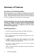
Summary of Features Key Features of 56K Message Modem 56K Message Modem is the first product to include features that allow the user to receive fax and voice messages without the intervention of the PC. 56K Message Modem features a bank of Flash Memory for this purpose. Messages can be received even when the PC is not switched on. Voice messages can be retrieved from a remote location. 56K Message Modem comes with specially designed application software.
• offers a voice channel feature that includes a built-in condenser microphone. • includes software designed specifically for use with 56K Message Modem. The software allows the user to take full advantage of all features in the product. Other software can be used for all standard modem functions. In order to use the autonomous features, however, we recommend using the software delivered with the product. Before You Begin From the factory, autonomous (independent) mode is not enabled.
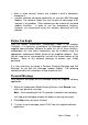
4. Once you have recorded your Personal Message, click on the ‘Download’ button in order to send your Personal Message to the modem. Full Message Your full message can be recorded using the supplied software application. 1. Within the Independent Mode Message Full Screen, click Record, and recite your Full Message. Note: If the recording limit of 15 seconds is reached, the recording will stop and a dialogue window will display a warning message. 2. Click Stop when you have finished. 3.
Remote Voice Retrieval - whilst the modem is in Independent mode To access your Voice messages remotely, you need to dial into the 56K Message Modem modem. Whilst the 'outgoing message' is being played, you must enter your pre-configured password on a touch-tone telephone handset (this can be set using the software application). You have three attempts to enter the correct password. If you fail to enter the correct password, the modem will 'abort' the call and go back 'on hook'.
Telephone Handset DTMF Digits for Remote Message Retrieval Digit(s) Function ------------------------------------------------------------------0 1) Stops playback of all voice messages 2) Stops the recording of your personal message 3) Stops playback of your personal message 1 Starts playback of all new messages 2 Starts playback of all stored messages, new and old 3 Skips to the next voice message 4 then 4 Deletes all old voice messages in memory 5 6 7 8 9 * # Enables/Disables Fax Forwarding feature Rep
1) Setup Independent Fax mode Set the phone number in the application (number is stored in the flash memory of the modem) and then enable/disable using the applicable button. 2) Fax forwarding dial up control (remote control is limited only to the enable/disable feature as follows) a) Enter your password and from the Main menu, press Ä to toggle the enable/disable fax forwarding feature. b) Confirmation of the enabling/disabling of this feature will be indicated by playing an opening/closing tone.
Part I : External Modem Installation Part I of this manual covers the installation of your external 56K Message Modem. The instructions are provided for both Windows 3.1/ 3.11 (hereafter jointly referred to as Windows 3.x) and Windows 95 users. Please refer to the section dealing with the operating system you use. The two sections are: Section A: External Installation with Windows 3.x (page 10) Section B: External Installation with Windows 95 (page12) Section A: External Modem Installation with Windows 3.
How to Connect the Modem 1. Turn off your computer and any attached devices, such as a printer. 2. Connect the serial cable to the modem and to the computer. When looking for the serial port label on the back of your computer, look for ports labelled COM, MODEM, RS-232, or SERIAL. DO NOT select AUX, GAME, LPT, or PARALLEL. NOTE: Remember which serial port you selected. This information will be necessary when installing your communications software. 3.
6. Turn your modem on. 7. Turn your computer on. 8. Start Windows 3.x. Congratulations! You are ready to start using your 56K Message Modem. Section B : External Modem Installation with Windows 95 You will need these items from your 3Com U.S.
How to Find Out Which Version of Windows 95 You Have 1. With the right mouse button, click the My Computer icon on your desktop. 2. Click Properties. In the “System Properties” screen, look at the system information under the General tab. (This information is circled in the screen shown to the right.) The number following the text “Microsoft Windows 95” will end with “950,” “950a,” or “950b.” This indicates your version of Windows 95. 3. Write this number down for later reference. 4. Click OK.
WARNING: The phone socket you’re going to use must be for an ANALOGUE phone line. Most office phones are wired through DIGITAL lines. Be sure you know what type of line you have. The modem will be damaged if you use a digital phone line. 5. If you wish to use your modem and phone through the same phone wall socket, plug your phone's lead into the modem's phone socket. It is labelled with a phone icon on the bottom of the case. Use an adapter cable if necessary.
How to Move Through the Screens You See When Windows Restarts If you have Windows 95 Version 950 or 950a: 1. When Windows 95 restarts, it should detect the modem. If it does, you will see the following screen. Click Driver from disk provided by hardware manufacturer. Then click OK. NOTE: If this screen does not appear, go to “If Plug and Play Does Not Detect Your Modem”. 2. Insert the driver disk into your disk drive. 3.
4. You can verify that the install was a success. When your desktop returns, click the Windows Start button and point to Settings. 5. Click Control Panel. 6. Double-click the Modems icon.
7. In the “Modems Properties” screen, you should see a description for your modem. This indicates that your new 3Com U.S. Robotics Message Modem is installed correctly. Note: If this screen does not appear, go to “If Plug and Play Does Not Detect Your Modem”.
8. Next, click the Diagnostics tab at the top of the “Modems Properties” screen. Write down the COM port number for your modem. You will need to know this setting when you install your communications software. 9. Click OK. If You Have Windows 95 Version 950b: 1. When Windows restarts, it should detect the modem, and you should see a screen like the one below. Insert the driver disk into your disk drive and click Next.
3. Once Windows finishes loading the information from the disk, you should verify that the modem installation was a success. When your desktop returns, click Start and point to Settings. Then click Control Panel. 4. Double-click the Modems icon.
5. In the “Modems Properties” screen, you should see a description of your modem. This indicates that your new 3Com U.S. Robotics Message Modem is installed correctly. Note: If this screen does not appear, go to “If Plug and Play Does Not Detect Your Modem”.
6. Next, click the Diagnostics tab at the top of the “Modems Properties” screen. Write down the COM port number for your modem. You will need to know this setting when you install your communications software. 7. Click OK. Congratulations! You are now ready to start using your 3Com U.S. Robotics Message Modem.
Part II : Beyond Setup Part II includes information which may not be necessary for installing your modem or voice/fax/data software, but will help to expand your knowledge of the modem and its capabilities.
Section A: Installing Voice/Fax/Data Software Your modem has been designed and tested using a wide range of communications software packages on the market. This section will walk you through some of the details you may need to know when installing communications software packages. Type of Modem Most communications software programs will ask you to select the type of modem you are using. Select a 3Com brand high speed modem. If that selection is not listed, pick Courier Dual Standard, V.32bis, or V. 34.
Flow Control • For hardware flow control (highly recommended), select RTS/CTS. • For software flow control, select XON/XOFF. NOTE: Disable the type of flow control (hardware or software) that you are not using. UART - Universal Asynchronous Receiver Transmitter (External Modems Only) If you are running Windows 3.x or you have upgraded your system from Windows 3.x to Windows 95, you can run MSD to determine your UART setting. In DOS, type MSD at the Windows directory prompt and then press ENTER.
Section B : Troubleshooting and Online Help Resources PROBLEM DIAGNOSIS POSSIBLE SOLUTION The computer or software will not recognize the modem. You may not be entering modem commands in the proper manner in Terminal mode. Type in all upper case (AT) or all lower case (at). If you are using an external modem, the COM port may not be enabled. Refer to the computer’s manual for information about enabling COM ports.
PROBLEM DIAGNOSIS POSSIBLE SOLUTION The modem will not go off hook to dial or does not answer the phone. You may have plugged your modem’s phone cord into a digital line. Plugging your modem’s phone cord into a digital phone line can damage the modem. Call your phone company if you are unsure whether or not your phone line is digital. The software you are using may not have auto answer enabled. Make sure the auto answer feature is enabled.
PROBLEM DIAGNOSIS POSSIBLE SOLUTION Your modem will not connect at 2400 bps with a 2400 bps modem. The modem you are trying to connect with, could be an older model that does not support error control. You can disable error control on your modem by typing the following command in the Terminal Mode: AT&M0 and press ENTER. Now try placing the call to the remote modem again. When finished, reset your modem to enable the error control features. In Terminal Mode, type ATZ and press ENTER.
PROBLEM DIAGNOSIS POSSIBLE SOLUTION Your communications software is reporting many cyclic redundancy check (CRC) errors and low characters per second (CPS). You may have a bad phone line. Try placing the call again. The phone company routes calls differently each time. Optimal flow control settings may not be enabled on your modem. Type this command in Terminal Mode to load the optimal hardware flow control settings, AT&F1 and press ENTER.
PROBLEM DIAGNOSIS POSSIBLE SOLUTION Your communications software is reporting many cyclic redundancy check (CRC) errors and low characters per second (CPS). If your communications program is DOS-based, you are running it under Windows, at the same time with other software. Conflicts between these programs may be causing the CRC errors. Close every program but the communications program. Errors are constantly occurring in your V.17 fax transmissions.
PROBLEM DIAGNOSIS POSSIBLE SOLUTION Your modem cannot achieve a 56K Internet connection. This modem is capable of 56Kbps downloads. However, the download speeds you experience may be lower due to varying line conditions and other factors. Uploads from users to server equipment travel at speeds up to 31.2 Kbps. An analogue phone line compatible with the ITU-T V.
If Plug and Play Does Not Detect Your Modem Try the following: 1. Click Windows 95 Start and click Shut Down. When asked if you wish to shut down your computer, click Yes. When Windows 95 indicates that it is safe to turn off your computer, turn it off and wait 15 seconds. Then turn the computer back on. Windows 95 may detect your modem upon this restart even if it did not detect the modem during the initial installation.
Online Help Resources Connecting to the 3Com BBS To connect to the 3Com Bulletin Board System, follow these steps: 1. Start your communications software. The software settings for the BBS are as follows: ANSI terminal emulation Data Bits: 8 Parity: None Stop Bits: 1 2. Put your computer in Terminal mode. Enter the following command: ATDT 01189692200 3. If this is your first time connecting to our BBS, you will be asked to enter your name and a password, as well as fill out a questionnaire. 4.
3Com offers a number of other on-line technical support options. Choose any one of the following if you need help with your new Modem. Internet FTP Provides free library containing the same files as the BBS site. FTP to ftp.usr.co.uk Internet On Demand Provides automatic technical support through a library containing product information, quick reference cards and installation help. To obtain an index of available documents, send blank e-mail to uksupport@usr.com.
Are You Still Having Problems? Should you encounter any difficulties with your 56K Message Modem faxmodem, refer to the manual first. Call or visit your dealer, if they are unable to assist you, contact the 3Com Technical Support Department from Monday through to Friday, during normal office hours on; Email address: uk_modemsupport@3com.com BBS: 0118 969 2200 Fax: 0870 844 4547 Tel: 0870 870 844 4546 Web site: http://www.3com.co.uk Upon contacting 3Com you will be issued with a Call Reference Number (CRN).
Section C : Glossary Cross references are printed in boldface. Cross references with items in the Command Summary, found in Section D: Technical Quick Reference, are printed in italics. analogue loopback A modem self-test in which data from the keyboard or an internal test pattern is sent to the modem's transmitter, turned into analogue form, looped back to the receiver, and converted back into digital form.
to when the data bits of a character begin and when they end. The addition of start/stop bits to each character serves this purpose. Auto Answer Sets the modem to pick up the phone line when it detects a certain number of rings. See S-register S0 in Section D: Technical Quick Reference. auto dial A process where your modem dials a call for you. The dialling process is initiated by sending an ATDT (dial tone) or ATDP (dial pulse) command followed by the telephone number to dial.
byte A group of binary digits stored and operated upon as a unit. In user documentation, the term usually refers to 8-bit units or characters. One kilobyte (KB) is equal to 1,024 bytes or characters; 640 KB indicates 655,360 bytes or characters. carrier A tone signifying a connection the modem can alter to communicate data across telephone lines. character A representation, coded in binary digits, of a letter, number, or other symbol.
data compression table A table containing values assigned for each character during a call under MNP5 data compression. Default values in the table are continually altered and built during each call: The longer the table, the more efficient throughput gained. data mode The mode in which the faxmodem is capable of sending and receiving data files. A standard modem without fax capabilities is always in data mode.
DTE Data Terminal (or Terminating) Equipment. A computer that generates or is the final destination of data. duplex Indicates a communications channel capable of carrying signals in both directions. See half duplex, full duplex. Electronic Industries Association (EIA) Group which defines electronic standards in the U.S. error control Various techniques that check the reliability of characters (parity) or blocks of data. V.
half duplex Signals will flow in both directions, but only one way at a time. In microcomputer communications, may refer to activation of the online local echo, which causes the modem to send a copy of the transmitted data to the screen of the sending computer. Hz Hertz, a frequency measurement unit used internationally to indicate cycles per second. ITU-T (International Telecommunications Union) An international organization that defines standards for telegraphic and telephone equipment.
nonvolatile memory (NVRAM) User-programmable random access memory whose data is retained when power is turned off. On the Modem, it includes four stored phone numbers and the modem settings. off/on hook Modem operations that are the equivalent of manually lifting a phone receiver (taking it off-hook) and replacing it (going on-hook).
Random Access Memory (RAM) Memory that is available for use when the modem is turned on, but that clears of all information when the power is turned off. The modem's RAM holds the current operational settings, a flow control buffer, and a command buffer. remote digital loopback A test that checks the phone link and a remote modem's transmitter and receiver. remote echo A copy of the data received by the remote system, returned to the sending system, and displayed on the screen.
throughput The amount of actual user data transmitted per second without the overhead of protocol information such as start/stop bits or frame headers and trailers. Compare with characters per second. V.8 The ITU-T standard specification that covers the initial handshaking process. V.17 fax An ITU-T standard for making facsimile connections at 14,400 bps, ,12,000 bps, 9600 bps, 7200 bps. V.
V.32 bis An ITU-T standard that extends the V.32 connection range: 4800, 7200, 9600, 12,000, and 14,400 bps. V.32 bis modems fall back to the next lower speed when line quality is impaired, fall back further as necessary, and also fall forward (switch back up) when line conditions improve. See online fall back/fall forward. V.34 An ITU-T standard that currently allows data rates as high as 33,600 and 28,800 bps. V.
Section D : Technical Quick Reference Section D includes information about: • • • • • • • Front Panel Lights (External Modems Only) Typing Commands Basic Data Commands Extended Data Commands S-Registers Fax Commands The Serial Interface (Cable Information) LED Indicators (Front Panel Lights) AA Auto Answer Answer mode: ON when register S0 is set to 1 or higher (Auto Answer), and when answering a call; OFF when modem originates a call. Light flashes when there is an incoming call.
SD Send Data Flashes when computer sends a data bit to modem. TR Data Terminal Ready ON if modem receives a DTR signal from computer. Always ON (modem ignores DTR) if the DTR override is ON (&D0). CS Clear to Send ON until modem lowers CTR when transmit data hardware flow control is enabled (&H1, &H3). MSG New Message Blinks red once for each new fax message. Blinks green once for each new voice message.
Typing Commands • Type commands in either upper or lower case, not a combination. Use the Backspace key to delete errors. (You cannot delete the original AT command since it is stored in the modem buffer.) • If a command has numeric options and you don’t include a number, zero is assumed. For example, if you type ATB, the command ATB0 is assumed. • Every command except A/,+++ and A> must begin with the AT prefix and be entered by pressing . • The maximum command length is 58 characters.
Basic Data Commands S Stop or restart help screens C or K Stop help screens $ Use in conjunction with D, S, or & commands (or just AT) to display a basic command list; online help. A Manual Answer: goes off hook in answer mode. Pressing any key aborts the operations. A/ Re-executes the last issued command. Used mainly to redial. This does not require the AT prefix or a Carriage Return.
, ; “ ! / W @ $ (Comma) Pause, See S8 definition; which it’s linked to. (Semicolon) Return to Command mode after dialling. Dials the letters that follow (in an alphabetical phone number). (Exclamation point) Flashes the switch hook. Delays for 125 ms. before proceeding with dial string. Wait for second dial tone (X2 or X4); linked to S6 register. Dials, waits for quiet answer, and continues (X3 or higher). Displays a list of Dial commands. En Sets local echo.
Mn On Qn L1 Low volume L2 Medium volume L3 High volume Operates speaker. M0 Speaker always OFF. M1 Speaker ON until CONNECT. M2 Speaker always ON. M3 Speaker ON after dial, until CONNECT. Returns online. O0 Returns online. O1 Returns online and retrains.Qn Displays/suppresses result codes. Q0 Q1 Q2 Displays result codes. Quiet mode; no result codes. Displays result codes only in Originate mode. Sr.b=n Sets bit .b of register r to n (0/OFF or 1/ON). Sr=n Sets register r to n.
Xn Sets result code displayed. Default is X4.
Xn (Continued) Xn Setting Result Codes (Continued) 256/CONNECT 28000 260/CONNECT 29333 264/CONNECT 30666 268/CONNECT 32000 180/CONNECT 33333 272/CONNECT 34666 276/CONNECT 36000 184/CONNECT 37333 280/CONNECT 38666 284/CONNECT 40000 188/CONNECT 41333 192/CONNECT 42666 196/CONNECT 44000 200/CONNECT 45333 204/CONNECT 46666 208/CONNECT 48000 212/CONNECT 49333 216/CONNECT 50666 220/CONNECT 52000 224/CONNECT 53333 228/CONNECT 54666 232/CONNECT 56000 236/CONNECT 57333 X0 X1 X2 X3 X4 • • • • • • • • • • • • •
Extended Data Commands &$ Displays a list of ampersand (&) commands. &An Enables/disables additional result code subsets. See Xn. &A0 ARQ result codes disabled &A1 ARQ result codes enabled &A2 Modulation indicator added &A3 Protocol indicators addedLAPM/MNP/NONE (error control) and V42bis/MNP5 (data compression) &Bn Manages modem’s serial port rate.
&Hn Sets Transmit Data (TD) flow control. See also &Rn. &H0 Flow control disabled &H1 Hardware flow control, Clear to Send (CTS) &H2 Software flow control, XON/XOFF &H3 Hardware and software flow control &In Sets Receive Data (RD) software flow control. See also &Rn. &I0 Software flow control disabled &I1 XON/XOFF signals to your modem and remote system &I2 XON/XOFF signals to your modem only &Kn Enables/disables data compression.
&N10 &N11 &N12 &N13 &N14 &N15 &N16 &N17 &N18 &N19 &N20 &N21 &N22 &N23 &N24 19,200 bps 21,600 bps 24,000 bps 26,400 bps 28,800 bps 31,200 bps 33,600 bps 28,000 bps 29,333 bps 30,666 bps 32,000 bps 33,333 bps 34,666 bps 36,000 bps 37,333 bps &N25 &N26 &N27 &N28 &N29 &N30 &N31 &N32 &N33 &N34 &N35 &N36 &N37 &N38 &N39 38,666 bps 40,000 bps 41,333 bps 42,666 bps 44,000 bps 45,333 bps 46,666 bps 48,000 bps 49,333 bps 50,666 bps 52,000 bps 53,333 bps 54,666 bps 56,000 bps 57,333 bps &Pn Sets pulse (rotary) dia
&Un Sets floor connect speed when &Un is set above 0. If the connection cannot be established above this speed, the modem will hang up. When &Un is used in conjunction with &Nn and &Nn is greater than 0, &Nn is the ceiling connect speed.. &U0 &U1 &U2 &U3 &U4 &U5 &U6 &U7 &U8 &U9 &U10 &U11 &U12 &U13 &U14 &U15 &U16 &U17 &U18 &U19 &U20 &N=0 &N>0 &U=0 Connects at best Connects at speed possible speed defined by &Nn. If connection cannot be established at this speed, the modem will hang up.
&Wn Writes current configuration to NVRAM templates. &W0 Modifies the NVRAM 0 template (Y0) &W1 Modifies the NVRAM 1 template (Y1) &Yn Sets break handling. &Y0 Destructive, but doesn’t send break &Y1 Destructive, expedited &Y2 Nondestructive, expedited &Y3 Nondestructive, unexpedited &Zn=s Writes phone number string s NVRAM at position n (n = 0−3). &Zn=L Writes last executed dial string to NVRAM at position n (n = 0−3). &Zn? Displays the phone number stored at position n (n = 0− 3).
S-Registers To change a setting, use the ATSr=n command, where r is the register and n is a decimal value from 0 − 255 (unless otherwise indicated). Register Default 58 Function S0 0 Sets the number of rings on which to answer in Auto Answer Mode. When set to 0, Auto Answer is disabled. S1 0 Counts and stores the number of rings from an incoming call. (S0 must be greater than 0.) S2 43 Stores the ASCII decimal code for the escape code character. Default character is +.
Register Default Function S8 2 Sets the duration, in seconds, for the pause (,) option in the Dial command. S9 6 Sets the required duration, in tenths of a second, of the remote modem’s carrier signal before recognition by the modem. S10 7 Sets the duration, in tenths of a second, that the modem waits to hang up after loss of carrier. This guard time allows the modem to distinguish between a line disturbance from a true disconnect (hang up) by the remote modem. .
Register Default Function S13 Bit-mapped register. Select the bit(s) you want on and set S13 to the total of the values in theValue column. For example, ATS13 = 17 enables bit 0 (value is 1) and bit 4 (value is 16). 0 Bit 0 1 Value 1 2 2 3 4 8 4 16 5 6 7 32 64 128 Result Reset when DTR drops. Reset non-MNP transmit buffer from 1.5K to 128 bytes.* Set backspace key to delete. On DTR signal, auto dial the number stored in NVRAM at position 0.
Register Default Function S14 0 Reserved S15 0 Bit-mapped register setup. To set the register, see instructions for S13. Bit 0 1 2 Result Disable ARQ/MNP for V.22. Disable ARQ/MNP for V.22bis. Disable ARQ/MNP V.32/V.32bis/V.32terbo. 3 8 Disable MNP handshake. 4 16 Disable MNP level 4. 5 32 Disable MNP level 3. 6 64 MNP incompatibility. 7 128 Disable V.42 operation. To disable V.
Register Default Function S21 10 Sets the length, in 10-millisecond units, of breaks sent from the modem to the computer; applies to MNP or V.42 mode only. S22 17 Stores the ASCII decimal code for the XON character. S23 19 Stores the ASCII decimal code for the XOFF character. S24 0 Reserved S25 20 Sets the duration, in hundredths of a second, that DTR must be dropped so that the modem doesn’t interpret a random glitch as a DTR loss.
Register Default Function 7 S28 0 8 128 Software compatibility mode. This setting disables the codes and displays the 9600 code instead. The actual rate of the call can be viewed on the ATI6 screen Used for unusual software incompatibilities. Some software may not accept 7200, 12,000, and 14,400 bps or greater result codes. Eliminates the V.32 answer tones for a faster connection. Default item, all times are in tenths of seconds. 255 Disables all connections except V.32 at 9600 bps.
Register Default Function S33 0 Bit 0 1 2 3 4 5 6 7 S34 0 Bit mapped register setup. To set registers, see instructions for S13. Bit S35-S37 64 Bit mapped register setup. To set the register, see the instructions for S13. Value Result 1 Disable 2400 symbol rate. 2 Disable 2743 symbol rate. 4 Disable 2800 symbol rate. 8 Disable 3000 symbol rate. 16 Disable 3200 symbol rate. 32 Disable 3429 symbol rate. 64 Reserved 128 Disable shaping.
Register Default Function S38 0 Sets an optional delay, in seconds, before a forced hang-up and clearing of the Transmit buffer when DTR drops during an ARQ call. This allows time for a remote modem to acknowledge receipt of all transmitted data before it is disconnected. The modem immediately hangs up when DTR drops. This option only applies to connections terminated by dropping DTR. If the modem receives the ATH command, it ignores S38 and immediately hangs up.
Fax Commands FCLASS=n Sets the mode of operation FCLASS=0 Data mode FCLASS=1 Group 3 Facsimile Service Class 1 mode FCLASS=2.0 Group 3 Facsimile Service Class 2.0 mode FCLASS? Displays the current FCLASS mode (See mode descriptions above) +FCLASS=? Displays the FCLASS mode options (See mode descriptions above) +FTS=n Stops the fax transmission. Then the modem waits for a specified time before OK appears on screen. The pause is set in 10 millisecond intervals.
+FTH=n Transmits data framed in the HDLC protocol using the modulation specified by n. (n = 3, 24, 48, 72, 96, 97, 98, 121,122, 145, or 146) Note: See the “Screen Messages” table at the end of this section for an explanation of messages that appear in response to this command. +FRH=n Receives data framed in the HDLC protocol using the modulation specified by n.
The Serial Interface The serial interface is a standard developed by the Electronic Industries Association (EIA). It defines the signals and voltages used when data is exchanged between a computer and a modem or serial printer. The entire standard covers many more functions than are used in most data communications applications.
Section E : CE Compliance Electromagnetic Compatibility This device complies with the following standards in accordance with European Directives 89/336/EEC: • Immunity EN 50082-1 06/92 • Emission EN 55022 class B 08/87 Safety (Low Voltage Directive) This device complies with the following standards in accordance with European Directive 91/263/EEC and 91/263/EEC: • EN 60950/A2 10/93 • EN 41003 08/93 The ports on this modem have the following safety status: • Telephone line connector = TNV • All other ports
CTR 21 Approval (in the UK and Ireland only) This equipment has been approved in accordance with Council Decision 98/482/EC for pan-European single terminal connection to the Public Switched Telephone Network (PSTN). However, due to differences between the individual PSTNs provided in different countries, the approval does not, of itself, give an unconditional assurance of successful operation on every PSTN network termination point.
Section F : Limited Warranty 3Com UK Limited warrants to the original consumer or other end user that this product is free from defects in materials or workmanship for the lifetime of the product. Upon proof of purchase, the product will be repaired or replaced (with the same or similar model) at our option, without charge for either parts or labour. This warranty shall not apply if the product is modified, tampered with, misused or subjected to abnormal working conditions.