® SpotCell Viewer User Manual version 2.
Table of Contents Introduction . . . . . . . . . . . . . . . . . . . . . . . . . . . . . . . . . . . . . . . . . . . . . . . . . . . . . .1 About this guide . . . . . . . . . . . . . . . . . . . . . . . . . . . . . . . . . . . . . . . . . . . . . . . .1 Compatibility . . . . . . . . . . . . . . . . . . . . . . . . . . . . . . . . . . . . . . . . . . . . . . . . . . .1 Getting Started . . . . . . . . . . . . . . . . . . . . . . . . . . . . . . . . . . . . . . . . . . . . . . . . . . .2 Packing List . . . . .
ii SpotCell Viewer 2
1 – Introduction SpotCell Viewer 2.4 is a PC based application that gives authorized carrier personnel remote access and control of deployed SpotCell solutions. It eliminates the need for on-site visits by carriers that use SpotCell adaptive repeaters to provide reliable, always on, in-building wireless connectivity in spaces up to 100,000 sq. ft. The SpotCell Viewer facilitates the widespread deployment of SpotCell solutions by providing carriers with real-time access to SpotCell products.
GETTING STARTED 2 – Getting Started 2.1 Packing List The SpotCell Viewer is shipped in a single box containing a: SpotCell Viewer 2.4 software CD that will be used to load the application on a customer provided computer. The User Guide is also included on the CD. 8 pin CAT 5 cable to connect the SpotCell to the customer computer. Modified RJ-45 to DB9 serial port adapter that connects the CAT 5 cable to the customer provided computer’s serial port. Quick Start guide. 2.
GETTING STARTED 2.5 Software Installation To install SpotCell Viewer 1. Insert the SpotCell Viewer 2.4 CD-ROM into the CD-ROM drive. 2. Follow the on-screen instructions. Note: To activate the “I ACCEPT” button on the Licence Agreement window, click inside the Licence Agreement text box. The SpotCell Viewer files will be installed, by default, in the C:\Program Files\SpotCell Viewer 2.4.
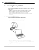
CONNECTING TO THE SPOTCELL CU 3 – Connecting to the SpotCell CU Although the SpotCell CU displays system status on the LCD, the Viewer is useful onsite to allow a user to: Graphically display on one screen all the information available on the LCD. Monitor the SpotCell system over a period of time by logging events. Change the SpotCell mode (Active/Install) or restart the system. Setup the SpotCell configuration, identification, and dial out fields for remote monitoring 3.
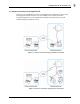
CONNECTING TO THE SPOTCELL CU 3.2 Remote connection to the SpotCell CU Viewer can be used remotely to access the SpotCell CU and perform all of the same monitoring and control functions that are available with an onsite connection. The following figures illustrate two possible methods of remotely accessing and troubleshooting the SpotCell system. Figure 1.1: Remote connection using a wireline connection. Figure 1.
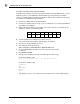
CONNECTING TO THE SPOTCELL CU To setup a connection using a wireline modem Although other modems may work, the wireline modem currently approved for use with SpotCell systems is the USRobotics USR325686E 56K V.92 External Faxmodem. Check the support page of the Spotwave Wireless web site (www.spotwave.com) for an up-to-date list of approved wireline modems. 1. Ensure the modem and CU are powered off. 2. Connect the modem and CU using an RJ-45 cable (max 50 ft.
CONNECTING TO THE SPOTCELL CU To setup a connection using a wireless modem 1. Follow the instructions included with the SpotCell Wireless Modem Installation kit (purchased separately) for mounting and connecting the wireless modem to the CU and DU. Wireless modems currently approved for use with the SpotCell system are: - AnyData iPORT(Model: EM III Dual) - Chameleon CTM110 Wireless Modem Check the support page of the Spotwave Wireless web site (www.spotwave.
INSTALL & ACTIVE MODE SYSTEM DISPLAYS 4 – Install & Active Mode System Displays Depending on whether the SpotCell system is in Install Mode or Active Mode, one of two main screens will appear when SpotCell Viewer is started. This section describes the system information displayed on these screens. 4.1 SpotCell Viewer – Install Mode 4.1.1 System Parameters System Mode 8 System mode indicates the SpotCell system is in Install by showing Install text in bold and greying out Active Mode text.
INSTALL & ACTIVE MODE SYSTEM DISPLAYS Note: In the case of the SpotCell 100 unit that operates in the 800 MHz cellular band, the Start and Stop Frequencies and Bandwidth are replaced by the Cellular Band (A or B) that is pre-programmed into the unit at the factory. Coverage Unit Display Replicates the messages shown on the LCD display located on the bottom edge of the Coverage Unit. 4.1.
INSTALL & ACTIVE MODE SYSTEM DISPLAYS 4.2 SpotCell Viewer - Active Mode The SpotCell Viewer main window for a SpotCell in Active Mode is shown below. Key differences from the Install Window are: System Mode displays Active (bold) instead of Install (greyed out). Donor Unit LED information is inactive when the unit is in Active mode. 10 Adaptive System Gains parameters are active Uplink displays the current gain of the uplink in dB. Downlink displays the current gain of the downlink in dB.
USING SPOTCELL VIEWER 5 – Using SpotCell Viewer This section describes the function of SpotCell Viewer’s tabbed page interface and how to use it. 5.1 The Connection Tab The Connection tab allows you to select a communication port, authenticate a session, change passwords, manage accounts, set timeouts, and open a Modem Terminal window. 5.1.1 Communication port The port used to communicate with the Coverage Unit can be COM port 1 to COM port 24.
USING SPOTCELL VIEWER 5.1.3 Authentication Login authentication is used to control user access to the SpotCell system. By default, there is one Administrator account already setup on the Spotcell system and up to 14 additional user accounts can be created. Administrative functions such as setting session time-outs or creating, editing, and deleting accounts are accessible only to the Administrator. To login (open a session for communication) 1. On the Connection tab, click Login. 2.
USING SPOTCELL VIEWER 5.1.5 Setting the timeout period A SpotCell Viewer session will automatically timeout after a specific period of inactivity. The timeout period can only be set by the adminstrator. To set the timeout 1. On the Connection tab, click Set Timeout. 2. Type the administrator username, password, and timeout period. The timeout range is 10 seconds to 30 minutes. The default timeout period is 2 minutes. 3. Click Set Timeout. 5.1.
USING SPOTCELL VIEWER 5.2 The Events Tab The Events tab allows you to view or log system events and events generated by the Coverage Unit’s adaptive algorithm. For a list and description of SpotCell log events see SpotCell Events on page 21. To clear the view window On the Events tab, click Clear. 5.2.1 Logging Events The Events tab view window limit is 1000 events and once this is reached, the oldest messages are lost as new events are displayed.
USING SPOTCELL VIEWER 5.3 The Control Tab The Control tab allows you to: force the SpotCell system to Install mode disable/enable dial out mode or the DU power supply restart the system from a known good state change Alarm phone numbers and Unit ID fields change the password (25 printable characters/case sensitive) 5.3.1 Password protection All functions of the Control tab require a password to be entered before the command can be completed.
USING SPOTCELL VIEWER 5.3.2 Forcing to Install mode When the SpotCell is in auto mode (normal operating mode), setting the system to install or active is controlled with the mode switch on the Coverage Unit (CU). Using Viewer, the SpotCell system can be forced to install mode by simply disabling auto mode. To force the system to Install Mode On the Control tab, clear the AUTO check box. Selecting the AUTO check box will return the system to auto mode (normal operating mode). 5.3.
USING SPOTCELL VIEWER To change the CU dial out number 1. On the Control tab, click Change Alarm Phone Number. 2. Type the new phone number. 5.3.7 CU identifiers Each SpotCell system has two field IDs that help identify the unit when connecting to a remote monitoring site. To change the CU Identifiers 1. On the Control tab, click Change Unit ID Field #1 or Change Unit ID Field #2. 2. Type any appropriate identifying text (up to 32 printable characters) in the New Identification field. 3.
USING SPOTCELL VIEWER 5.4 The Configure tab The Configure tab is only available when connected to the SpotCell 163 or SpotCell 263 product. The Configure tab is used to view or modify the prefered channels and to force the system to use the preferred channels for scanning. To program the preferred channels 1. On the Configure tab, click Modify. 2. Set the preffered channels, and click OK. To use preferred channels for scanning On the Configure tab, select the Enable Exclusive Channel List check box.
Appendix A – Menu Commands A.1 File Menu A.1.1 Exit command To exit the SpotCell Viewer application Click on the File drop-down menu and select Exit. A.2 Help Menu The Help drop-down menu contains the Help and About SpotCell Viewer command. A.2.1 Help command Each item in the main window has an associated help file topic. To view the Help file, click on the Help drop-down menu and select Help. To obtain details about a SpotCell Viewer parameter, click on the desired parameter. A.2.
20 SpotCell Viewer 2
Appendix B – SpotCell Events B.1 SpotCell external events Events generated from external inputs to the SpotCell product are: Event Description Troubleshooting Active Signal Undetectable: Searching The active base station signal is not present. The adaptive algorithm is searching for an inband signal. Coverage is not provided during this period. When an Active Signal is found, the event notification is cleared. Coverage is provided after the event is cleared. Realign the DU.
B.2 SpotCell internal events Events generated as a result of internal built-in-tests are: Event Description Troubleshooting CU Voltage Out-of-range: Out of Service The CU power supply voltage is outside the rated operating range. Coverage is not provided during this period. When the out-of-range condition is no longer present, the event notification is cleared. Coverage is provided after the event is cleared. Check the power supply connection to the CU.
www.spotwave.com Spotwave Wireless Inc. 1 Hines Road, Ottawa ON K2K 3C7 Canada © 2005 Spotwave Wireless Inc. All rights reserved. Printed in Canada Spotwave and SpotCell are trademarks of Spotwave Wireless Inc. Patents pending.