
Instruction Manual


While connecting the machine to the mains power, it is raccomended to never disconnect existing ground cable.
The fact of disconnecting or modifing existing cables voids the warranty and can cause troubles or accidents related to the
temperature control.
08
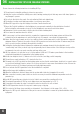
DESCRIPTION OF INPUT AND OUTPUT CONNECTIONS
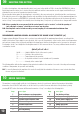
Discrete signals port
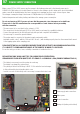
The discrete signal port is hosted on a multiple way screwed connector, visible on the right
side of Fig. 1.
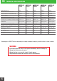
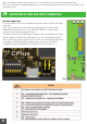
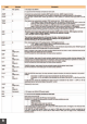
In Tab. 1 is indicated the pinout, along with some important notes about each signal.
IMPORTANT: the descriptions in Tab. 1 are valid if DIP-SWITCH 4 is on OFF position
(passive security, relays are normally NOT active).
The signals present on this port will always be available to the user and will work in parallel
with the commands received by the serial interface. In no case a voltage greater than the
board’s power supply should be applied to any pin of this port, except for relay outputs that
can manage up to 60V, 500mA. Some interface options depend on S3 (Dip Switch)
configuration and W1 and W2 jumpers: Fig.2 shows their position on the board.
Fig. 1
8