
Technical data


Adding Uponor Interface I-75/76 to the Uponor Control System
provides:
• Centralized management of the underfl oor system
• Rapid display and update of system settings
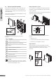
The illustration below shows the exterior and interior of Uponor
Interface I-75/76.
The table below describes the numbered items in the
illustration.
Item Description
1
Screen
2
Navigation keys
3
Fault indicator
4
Reset button
5
Data stick connection
9.1 Use navigation keys
Each of the fi ve navigation keys on Uponor Interface I-75/76
has dual functions, as described in the table below.
Key Functions
Displays next menu or Moves to next fi eld
Displays previous
menu. Pressing and
holding in a menu
screen displays main
Uponor screen
or Moves to previous
fi eld
Moves to line above or Increases value
Moves to line below or Decreases value
Displays next screen or Confi rms selections;
displays screen of
current menu
• Press any navigation key to activate backlighting.
• Press OK to go to the main menu.
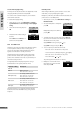
9.2 Interface I-75/76 main screen
The table below describes icons displayed on the Uponor main
screen:
Icon Description
Holiday Mode
Alarm/error message
Temperature set point
Temperature measured
Floor temperature (when fl oor sensor is installed)
Batteries suffi ciently charged
Batteries discharged, replace batteries
Basic access level (Interface I-76 only)
Advanced access level (Interface I-76 only)
The outdoor temperature is displayed if the system has
Thermostat T-54 Public with an outdoor sensor installed.
9.3 Interface I-75/76 main menu
The table below describes the numbered items in the example.
Item Description
1
Upper banner displays menu heading
2
Information zone: the selected line is highlighted
3
Scroll bar
9. Operate Uponor Interface I-75/76
2
3
1
36
UPONOR CONTROL SYSTEM – INSTALLATION AND OPERATION MANUAL
UK English