
Technical data


7. Operate Uponor Controller C-55/56
The table below describes the status of the controller LEDs.
LED Status
Power LED Power LED of the controller is always on
and fl ashes when a problem occurs, such
as:
•
Loss of radio transmission from a
thermostat for more than 3 hours
•
Low batteries in a thermostat
•
Short-circuited actuator
•
Cover alarm (Thermostat T-54 Public)
Channel LEDs
•
On – actuators activated
•
One fl ash a second – waiting for
thermostat to be registered
•
Two fl ashes a second – Alarm
•
One fl ash every two seconds – waiting
for actuators to be activated
•
Off – no demand for heating or cooling
Flashing AC
power LED
A fl ashing AC power LED indicates an
alarm or an error message.
Automatic exercise function
Uponor Controller C-55/56 has an automatic exercise function
that is scheduled to be performed weekly. The exercise is
designed to prevent the pump and actuators from seizing if they
have not been activated for a long period.
If the system includes an Interface I-75/76, the exercise
function can be used at any time.
Clean controller
Use a dry, soft cloth to clean Uponor Controller C-55/56.
Do not use detergent or any other liquids.
If no Uponor Interface I-75/76 is connected to the system, then
Uponor recommends occasionally opening the controller cover
to check for alarms. The controller LED fl ashes continuously
for general alarms, so it is necessary to determine which
thermostats are issuing alarms.
7.1 Normal controller operation
During normal operation the power LED of the controller is on.
All the channel LEDs are off when there is no demand for
heating or cooling. The LEDs come on when the corresponding
actuators are activated.
No more than six actuators can be in the opening process at
the same time. They open sequentially. The LED of the seventh
actuator and followings fl ash while they are waiting for the
previous actuators to be fully open.
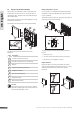
Controller LEDs
The illustration below shows the position of the controller LEDs.
The table below describes the numbered items in the
illustration.
Item Description
1
Test button and LED
2
Power LED
3
Channel LEDs
1
2
3
STOP
31
UPONOR CONTROL SYSTEM – INSTALLATION AND OPERATION MANUAL
UK English