
Installation and Operation Manual
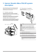
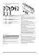
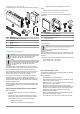
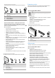
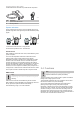
Table Of Contents
- Uponor Smatrix Wave PULSE
- Table of contents
- 1 Copyright and disclaimer
- 2 Preface
- 3 Uponor Smatrix Wave PULSE system description
- 3.1 System overview
- 3.2 Example of a system
- 3.3 Uponor Smatrix Wave PULSE components
- 3.4 Accessories
- 3.5 Functions
- 4 Install Uponor Smatrix Wave PULSE
- 5 Install Uponor Smatrix Wave PULSE room controller
- 5.1 Placement of room controller
- 5.2 Connect optional slave module
- 5.3 Attach room controller to the wall
- 5.4 Install room controller antenna
- 5.5 Install communication module
- 5.6 Connect actuators to room controller
- 5.7 Connect electrical underfloor heating
- 5.8 Connect input to room controller GPI
- 5.9 Connect output to room controller relays
- 5.10 Connect room controller to AC power
- 5.11 Test actuators
- 6 Install Uponor Smatrix Wave room thermostat
- 6.1 Uponor Smatrix Wave T-161
- 6.2 Uponor Smatrix Wave T-163
- 6.6 Uponor Smatrix Wave T-169
- 9 Install Uponor Smatrix Wave relay module
- 9.1 Placement of relay module
- 9.2 Attach relay module to the wall
- 9.3 Connect output to relay module
- 9.4 Register relay module to room controller
- 9.5 Use relay module to connect fan coils
- 9.6 Use relay module for time delayed two stage additional cooling (requires communication module)
- 10 Install another Uponor Smatrix room controller in the system
- 11 Finishing installation
- 12 Operate Uponor Smatrix Wave PULSE room controller
- 12.1 Principle of operation
- 12.2 Normal operation without optional scheduling programs
- 12.3 Operation with scheduling programs
- 12.4 Run mode
- 12.5 Room controller LEDs
- 12.6 Reset the controller
- 12.7 Unregister room controller channels
- 13 Operate Uponor Smatrix PULSE communication module
- 14 Operate Uponor Smatrix Wave thermostats
- 16 Maintenance
- 17 Troubleshooting
- 17.1 General
- Fluctuating floor temperature
- The room is too cold (or too warm in cooling mode)
- Thermostat setpoint is too low
- The temperature displayed on the thermostat changes after the thermostat is moved
- Installation report and room controller/channel numbering on the thermostat label doesn't match
- Installation report and room controller/channel numbering on the thermostatic head label doesn't match
- White indicator cannot be seen in window of an actuator
- Setpoint temperature displayed in the room information menu is lower than the temperature set on the thermostat
- ECO mode
- The room is too warm (or too cold in cooling mode)
- The floor is cold
- All rooms are cold (or warm in cooling mode)
- Disturbing noise from the pump at the same time every week
- No communication
- Communication failure between the room controllers
- 17.2 Troubleshooting after installation
- 17.3 Digital thermostat alarms/problems
- 17.4 Analogue thermostat alarms/problems
- 17.5 Thermostatic head alarms/problems
- The text “bAt” is shown in the display
- The text “POS” is shown in the display
- The display is off
- Radio transmission icon is displayed but the signals are received only when the thermostatic head is close to the antenna
- No radio transmission icon is displayed on thermostatic head screen when buttons are pressed
- 17.6 Communication module alarms/problems
- Alarms shown in Uponor Smatrix PULSE app
- The communication module has lost communication with Uponor cloud services
- The communication module has re-established communication with Uponor cloud services
- Software update failed
- Thermostatic head valve position error
- Floor temperature limit reached
- Faulty temperature sensor
- Faulty external temperature sensor
- Faulty relative humidity sensor
- Faulty Comfort/ECO switch
- Relative humidity sensor limit
- Faulty outdoor temperature sensor
- Faulty heating/cooling supply sensor
- External heating/cooling switch lost
- General systems alarm
- High supply temperature
- Low supply temperature
- Thermostat tamper alarm
- Low average temperature
- Relay module lost
- The communication module does not start
- Bad Wi-Fi connection
- Alarms shown in Uponor Smatrix PULSE app
- 17.7 Room controller alarms/problems
- 17.8 Contact the installer
- 17.9 Installer instructions
- 17.1 General
- 18 Technical data

Components of the room controller
The illustration below shows the room controller and its components.
B
A
D
E F
C
CD0000025
Item Description
A Uponor Smatrix Wave PULSE X-265
B Antenna
C Transformer module
D DIN rail
E Mounting material
F End cap
Communication module
Note
Setting up a system with a communication module
requires a mobile device (smart phone/tablet).
Note
It is recommended to attach the communication module
to a wall outside of the cabinet when using Wi-Fi
connection.
The communication module enables local and remote (requires
connection to Uponor cloud services) access to the room controller
from a mobile device (using the Uponor Smatrix PULSE app).
The communication module contains both an antenna module (for
internal communication with thermostats and such), and a local
network module for Wi-Fi or ethernet communication.
The app acts as a link between the user/installer and the room
controller(s) running in the system, displaying information and
enabling simplified programming of all relevant system settings. The
Uponor Smatrix PULSE app can be downloaded from Google Play
(Android) or App Store (iOS).
The Uponor Smatrix Wave system can be operated without the app
and communication module, but only with basic functionality (using
the thermostats).
Uponor Smatrix PULSE Communication Module
Main characteristics:
• Uponor Smatrix PULSE app connectivity via either Wi-Fi or
ethernet.
• Internal radio antenna for communication within the Uponor
Smatrix system (eliminates the need for the regular antenna).
• Extra functionality (using Uponor Smatrix PULSE app):
-
Heating/cooling settings
-
Extra relay functionality (chiller, dehumidifier etc).
-
Integrate up to four room controller into one system.
Options:
• Cabinet or wall mounted (DIN rail or supplied screws).
Components of the communication module
The illustration below shows the communications module and its
components.
BA DC
CD0000026
Item Description
A Uponor Smatrix PULSE Com R-208
B Optional back mount for DIN-rail
C Communication cable, RJ45
D Mounting hardware
Thermostats
Note
The thermostat is affected by the temperature of the
surrounding surfaces as well as the ambient air
temperature.
The thermostats communicate with the room controller through radio
transmissions and are used either individually or in combination with
each other.
The following Uponor Smatrix thermostats can be used in the system:
• Uponor Smatrix Wave T-161, Page 8
• Uponor Smatrix Wave T-169, Page 10
Uponor Smatrix Wave T-161
The thermostat is designed to be as small as possible, and still able
to control the room temperature.
Main characteristics:
• Operative sensor for increased comfort.
• Adjust setpoint temperature via the Uponor Smatrix PULSE app
(requires communication module).
• Setpoint range is 5 – 35 °C (maximum and minimum setting may
be limited by other system settings).
• Optional floor temperature sensor can be connected to the
thermostat. Floor temperature limitation settings (maximum and
minimum) are only available using the Uponor Smatrix PULSE
app (requires communication module). Otherwise system
defaults are used to limitation.
• Relative humidity limit indicated in the Uponor Smatrix PULSE
app (requires communication module).
• Can be placed up to 30 meters away from the room controller.
8
|
Uponor Smatrix Wave PULSE
|
Installation and operation manual