
Installation and Operation Manual
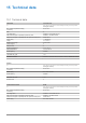
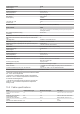
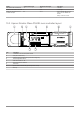
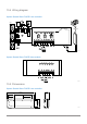
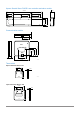
Table Of Contents
- Uponor Smatrix Wave PULSE
- Table of contents
- 1 Copyright and disclaimer
- 2 Preface
- 3 Uponor Smatrix Wave PULSE system description
- 3.1 System overview
- 3.2 Example of a system
- 3.3 Uponor Smatrix Wave PULSE components
- 3.4 Accessories
- 3.5 Functions
- 4 Install Uponor Smatrix Wave PULSE
- 5 Install Uponor Smatrix Wave PULSE room controller
- 5.1 Placement of room controller
- 5.2 Connect optional slave module
- 5.3 Attach room controller to the wall
- 5.4 Install room controller antenna
- 5.5 Install communication module
- 5.6 Connect actuators to room controller
- 5.7 Connect electrical underfloor heating
- 5.8 Connect input to room controller GPI
- 5.9 Connect output to room controller relays
- 5.10 Connect room controller to AC power
- 5.11 Test actuators
- 6 Install Uponor Smatrix Wave room thermostat
- 6.1 Uponor Smatrix Wave T-161
- 6.2 Uponor Smatrix Wave T-163
- 6.6 Uponor Smatrix Wave T-169
- 9 Install Uponor Smatrix Wave relay module
- 9.1 Placement of relay module
- 9.2 Attach relay module to the wall
- 9.3 Connect output to relay module
- 9.4 Register relay module to room controller
- 9.5 Use relay module to connect fan coils
- 9.6 Use relay module for time delayed two stage additional cooling (requires communication module)
- 10 Install another Uponor Smatrix room controller in the system
- 11 Finishing installation
- 12 Operate Uponor Smatrix Wave PULSE room controller
- 12.1 Principle of operation
- 12.2 Normal operation without optional scheduling programs
- 12.3 Operation with scheduling programs
- 12.4 Run mode
- 12.5 Room controller LEDs
- 12.6 Reset the controller
- 12.7 Unregister room controller channels
- 13 Operate Uponor Smatrix PULSE communication module
- 14 Operate Uponor Smatrix Wave thermostats
- 16 Maintenance
- 17 Troubleshooting
- 17.1 General
- Fluctuating floor temperature
- The room is too cold (or too warm in cooling mode)
- Thermostat setpoint is too low
- The temperature displayed on the thermostat changes after the thermostat is moved
- Installation report and room controller/channel numbering on the thermostat label doesn't match
- Installation report and room controller/channel numbering on the thermostatic head label doesn't match
- White indicator cannot be seen in window of an actuator
- Setpoint temperature displayed in the room information menu is lower than the temperature set on the thermostat
- ECO mode
- The room is too warm (or too cold in cooling mode)
- The floor is cold
- All rooms are cold (or warm in cooling mode)
- Disturbing noise from the pump at the same time every week
- No communication
- Communication failure between the room controllers
- 17.2 Troubleshooting after installation
- 17.3 Digital thermostat alarms/problems
- 17.4 Analogue thermostat alarms/problems
- 17.5 Thermostatic head alarms/problems
- The text “bAt” is shown in the display
- The text “POS” is shown in the display
- The display is off
- Radio transmission icon is displayed but the signals are received only when the thermostatic head is close to the antenna
- No radio transmission icon is displayed on thermostatic head screen when buttons are pressed
- 17.6 Communication module alarms/problems
- Alarms shown in Uponor Smatrix PULSE app
- The communication module has lost communication with Uponor cloud services
- The communication module has re-established communication with Uponor cloud services
- Software update failed
- Thermostatic head valve position error
- Floor temperature limit reached
- Faulty temperature sensor
- Faulty external temperature sensor
- Faulty relative humidity sensor
- Faulty Comfort/ECO switch
- Relative humidity sensor limit
- Faulty outdoor temperature sensor
- Faulty heating/cooling supply sensor
- External heating/cooling switch lost
- General systems alarm
- High supply temperature
- Low supply temperature
- Thermostat tamper alarm
- Low average temperature
- Relay module lost
- The communication module does not start
- Bad Wi-Fi connection
- Alarms shown in Uponor Smatrix PULSE app
- 17.7 Room controller alarms/problems
- 17.8 Contact the installer
- 17.9 Installer instructions
- 17.1 General
- 18 Technical data

Faulty heating/cooling supply sensor
• An error has been detected with the heating/cooling supply
sensor connected to the public thermostat.
-
Check the connection of the heating/cooling supply
sensor.
-
Disconnect the external sensor and check it with an
ohmmeter. Make sure the value aligns with the
temperatuer sensor diagram.
If the error persists, replace the external sensor.
External heating/cooling switch lost
• The room controller is having problem communicating with the
system device configured as an external switch.
Force the thermostat to transmit by opening/closing the external
switch.
If the problem persists:
-
The system device thermostat is out of range. T
ry to find a
new position for the system device thermostat and/or the
antenna, or, if possible, move any shielding objects
-
New installations in building shield radio signals (for
example, metal door safe). Try to find a new position for
the system device thermostat and/or the antenna, or, if
possible, move the shielding object
-
Low radio signal detected (sporadic communication with
the connected unit). The transmitter is working with
reduced signal intensity
-
The transmitter in the system device thermostat is faulty.
Replace the thermostat
General systems alarm
• Check the external source connected to the GPI and investigate
why the general systems alarm has tripped.
High supply temperature
This alarm is only shown if Supply diagnostics is running (the function
requires connection to Uponor cloud services).
• The supply temperature is too high.
Check the heat source, or supply temperature controller, to lower
the supply temperature. Contact the installer if the problem
persists.
Low supply temperature
This alarm is only shown if Supply diagnostics is running (the function
requires connection to Uponor cloud services).
• The supply temperature is too low.
Check the heat source, or supply temperature controller, to
increase the supply temperature. Other possible causes may be
too low flow on the supply line, or a malfunctioning circulation
pump. Contact the installer if the problem persists.
Low average temperature
• Average temperature in the system is lower than set limit (se
Installer settings).
The average temperature is calculated using selected rooms
(activated in room settings).
This may be due to one of the following probable causes:
-
Thermostat setpoints are too low. Increase the setpoints
on the thermostats in the rooms where the average
temperature is calculated
-
The supply temperature is too low. Check the heat source,
or supply temperature controller, to increase the supply
temperature. Other possible causes may be too low flow
on the supply line, or a malfunctioning circulation pump.
Contact the installer if the problem persists
-
The average temperature limit is too low. Increase the
average temperature limit
-
Other factors, such as opened windows/doors etc. Close
doors/windows which might af
fect the measured
temperature
Relay module lost
• Communication failure with the relay module.
-
Make sure the relay module is powered on.
-
Register the relay module again to the master room
controller
.
Otherwise contact the installer.
The communication module does not start
• There is not power to the communication module.
1. Check the communication cable between the room
controller and communication module, make sure it is
connected properly.
2. Replace the communication cable if needed.
3. Contact the installer or replace the communication module
Bad Wi-Fi connection
• The communication module looses connection with the Wi-Fi
network.
-
Connect the communication module to the local network
using an Ethernet cable.
For more information see, 5. Connect the optional ethernet
cable, Page 25.
14.6 Room controller alarms/
problems
See Controller LEDs, Page 76, for more information about the room
controller LED status.
The power LED and channel LED on the room
controller flashes
• The antenna is out of position or a wire is disconnected
-
Install the antenna in a correct position with the cable
correctly connected
Uponor Smatrix Wave PULSE
|
Installation and operation manual
|
74