
Installation and Operation Manual
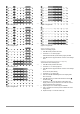
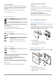
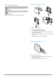
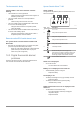
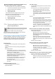
Table Of Contents
- Uponor Smatrix Wave PULSE
- Table of contents
- 1 Copyright and disclaimer
- 2 Preface
- 3 Uponor Smatrix Wave PULSE system description
- 3.1 System overview
- 3.2 Example of a system
- 3.3 Uponor Smatrix Wave PULSE components
- 3.4 Accessories
- 3.5 Functions
- 4 Install Uponor Smatrix Wave PULSE
- 5 Install Uponor Smatrix Wave PULSE room controller
- 5.1 Placement of room controller
- 5.2 Connect optional slave module
- 5.3 Attach room controller to the wall
- 5.4 Install room controller antenna
- 5.5 Install communication module
- 5.6 Connect actuators to room controller
- 5.7 Connect electrical underfloor heating
- 5.8 Connect input to room controller GPI
- 5.9 Connect output to room controller relays
- 5.10 Connect room controller to AC power
- 5.11 Test actuators
- 6 Install Uponor Smatrix Wave room thermostat
- 6.1 Uponor Smatrix Wave T-161
- 6.2 Uponor Smatrix Wave T-163
- 6.6 Uponor Smatrix Wave T-169
- 9 Install Uponor Smatrix Wave relay module
- 9.1 Placement of relay module
- 9.2 Attach relay module to the wall
- 9.3 Connect output to relay module
- 9.4 Register relay module to room controller
- 9.5 Use relay module to connect fan coils
- 9.6 Use relay module for time delayed two stage additional cooling (requires communication module)
- 10 Install another Uponor Smatrix room controller in the system
- 11 Finishing installation
- 12 Operate Uponor Smatrix Wave PULSE room controller
- 12.1 Principle of operation
- 12.2 Normal operation without optional scheduling programs
- 12.3 Operation with scheduling programs
- 12.4 Run mode
- 12.5 Room controller LEDs
- 12.6 Reset the controller
- 12.7 Unregister room controller channels
- 13 Operate Uponor Smatrix PULSE communication module
- 14 Operate Uponor Smatrix Wave thermostats
- 16 Maintenance
- 17 Troubleshooting
- 17.1 General
- Fluctuating floor temperature
- The room is too cold (or too warm in cooling mode)
- Thermostat setpoint is too low
- The temperature displayed on the thermostat changes after the thermostat is moved
- Installation report and room controller/channel numbering on the thermostat label doesn't match
- Installation report and room controller/channel numbering on the thermostatic head label doesn't match
- White indicator cannot be seen in window of an actuator
- Setpoint temperature displayed in the room information menu is lower than the temperature set on the thermostat
- ECO mode
- The room is too warm (or too cold in cooling mode)
- The floor is cold
- All rooms are cold (or warm in cooling mode)
- Disturbing noise from the pump at the same time every week
- No communication
- Communication failure between the room controllers
- 17.2 Troubleshooting after installation
- 17.3 Digital thermostat alarms/problems
- 17.4 Analogue thermostat alarms/problems
- 17.5 Thermostatic head alarms/problems
- The text “bAt” is shown in the display
- The text “POS” is shown in the display
- The display is off
- Radio transmission icon is displayed but the signals are received only when the thermostatic head is close to the antenna
- No radio transmission icon is displayed on thermostatic head screen when buttons are pressed
- 17.6 Communication module alarms/problems
- Alarms shown in Uponor Smatrix PULSE app
- The communication module has lost communication with Uponor cloud services
- The communication module has re-established communication with Uponor cloud services
- Software update failed
- Thermostatic head valve position error
- Floor temperature limit reached
- Faulty temperature sensor
- Faulty external temperature sensor
- Faulty relative humidity sensor
- Faulty Comfort/ECO switch
- Relative humidity sensor limit
- Faulty outdoor temperature sensor
- Faulty heating/cooling supply sensor
- External heating/cooling switch lost
- General systems alarm
- High supply temperature
- Low supply temperature
- Thermostat tamper alarm
- Low average temperature
- Relay module lost
- The communication module does not start
- Bad Wi-Fi connection
- Alarms shown in Uponor Smatrix PULSE app
- 17.7 Room controller alarms/problems
- 17.8 Contact the installer
- 17.9 Installer instructions
- 17.1 General
- 18 Technical data

Customise user defined program for a full week
Note
This method resets the current user defined program to
factory defaults.
To customise the user defined program:
1. Press OK to enter parameter edit mode.
2. Use buttons - or + to select program
U.
3. Press and hold OK until day 1 and 00:00 appears on the display.
4. Press OK to switch the marked interval between Comfort (
)
and ECO mode ( ).
5. Use buttons - or + to move the marker (at the bottom of the
display). When moving the marker from one interval to another
save the selected mode to that interval.
6. Repeat steps 4 and 5 until the display shows 23:30.
7. Press
+ to finalize programming the current day.
The text Copy Yes appears (Yes is flashing).
8. Use buttons - or + to select Yes or No and press OK to confirm.
Yes: Copy the setting of the current day to the next. Repeat for
every day that should be identical.
No: Create a new scheduling interval for the following day. Then
repeat steps 4 through 8 until the whole week is programmed.
9. The display returns to the settings menu when the final day is
done.
02 Heating/cooling changeover
This menu is not visible if the thermostat is registered to a room
controller. Heating/cooling changeover will be controlled by a physical
heating/cooling switch or in the Uponor Smatrix PULSE app (requires
communication module).
03 ECO mode setback temperature
Default: 4 ˚C
Setting range: 0 – 11 ˚C, 0.5 ˚C increments
In this menu the setback temperature for whenever the channel is in
ECO mode is set.
The setting adjusts the current setpoint with the set value. In heating
mode the setpoint is reduced, and in cooling mode it is increased.
If the setback temperature is set to 0, the thermostat will remain
unaffected if a program sets the system in ECO mode.
This menu is not visible if a communication module is connected to
the system. The setting is then available in the Uponor Smatrix
PULSE app.
See Change settings, Page
90, for how to change the setting.
04 Control mode
In this menu control mode for the thermostat is set.
If an external sensor is connected to the thermostat, a control mode
must be chosen to accommodate the extra functionality of the sensor.
Current control mode is displayed (RT, RFT
, RS or RO).
See Change settings, Page 90, for how to change the setting.
Uponor Smatrix Wave T
-169
Symbol Description
Room temperature sensor
Room temperature sensor and floor temperature
sensor
Remote sensor
Room temperature sensor and outdoor temperature
sensor
05 High floor temperature limitation
Note
This parameter cannot be set lower than the set value in
settings menu 06 Low floor temperature limitation.
Default: 26 ˚C
Setting range: 20 – 35 ˚C, 0.5 ˚C increments
In this menu a limit on the maximum allowable floor temperature is
set.
This menu is only visible if control mode RFT is activated in settings
menu 04. For systems with a communication module this menu only
shows the set value, changes are done in the Uponor Smatrix
PULSE app.
See Change settings, Page 90, for how to change the setting.
06 Low floor temperature limitation
Note
This parameter cannot be set higher than the set value in
settings menu 05 High floor temperature limitation.
Default: 20 ˚C
Setting range: 10 – 30 ˚C, 0.5 ˚C increments
In this menu a limit on the minimum allowable floor temperature is
set.
This menu is only visible if control mode RFT is activated in settings
menu 04. For systems with a communication module this menu only
shows the set value, changes are done in the Uponor Smatrix
PULSE app.
See Change settings, Page 90, for how to change the setting.
Uponor Smatrix Wave PULSE
|
Installation and operation manual
|
64