
Installation and Operation Manual
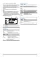
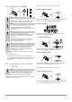
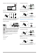
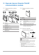
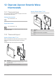
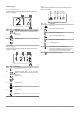
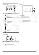
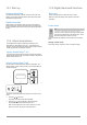
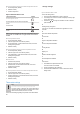
Table Of Contents
- Uponor Smatrix Wave PULSE
- Table of contents
- 1 Copyright and disclaimer
- 2 Preface
- 3 Uponor Smatrix Wave PULSE system description
- 3.1 System overview
- 3.2 Example of a system
- 3.3 Uponor Smatrix Wave PULSE components
- 3.4 Accessories
- 3.5 Functions
- 4 Install Uponor Smatrix Wave PULSE
- 5 Install Uponor Smatrix Wave PULSE room controller
- 5.1 Placement of room controller
- 5.2 Connect optional slave module
- 5.3 Attach room controller to the wall
- 5.4 Install room controller antenna
- 5.5 Install communication module
- 5.6 Connect actuators to room controller
- 5.7 Connect electrical underfloor heating
- 5.8 Connect input to room controller GPI
- 5.9 Connect output to room controller relays
- 5.10 Connect room controller to AC power
- 5.11 Test actuators
- 6 Install Uponor Smatrix Wave room thermostat
- 6.1 Uponor Smatrix Wave T-161
- 6.2 Uponor Smatrix Wave T-163
- 6.6 Uponor Smatrix Wave T-169
- 9 Install Uponor Smatrix Wave relay module
- 9.1 Placement of relay module
- 9.2 Attach relay module to the wall
- 9.3 Connect output to relay module
- 9.4 Register relay module to room controller
- 9.5 Use relay module to connect fan coils
- 9.6 Use relay module for time delayed two stage additional cooling (requires communication module)
- 10 Install another Uponor Smatrix room controller in the system
- 11 Finishing installation
- 12 Operate Uponor Smatrix Wave PULSE room controller
- 12.1 Principle of operation
- 12.2 Normal operation without optional scheduling programs
- 12.3 Operation with scheduling programs
- 12.4 Run mode
- 12.5 Room controller LEDs
- 12.6 Reset the controller
- 12.7 Unregister room controller channels
- 13 Operate Uponor Smatrix PULSE communication module
- 14 Operate Uponor Smatrix Wave thermostats
- 16 Maintenance
- 17 Troubleshooting
- 17.1 General
- Fluctuating floor temperature
- The room is too cold (or too warm in cooling mode)
- Thermostat setpoint is too low
- The temperature displayed on the thermostat changes after the thermostat is moved
- Installation report and room controller/channel numbering on the thermostat label doesn't match
- Installation report and room controller/channel numbering on the thermostatic head label doesn't match
- White indicator cannot be seen in window of an actuator
- Setpoint temperature displayed in the room information menu is lower than the temperature set on the thermostat
- ECO mode
- The room is too warm (or too cold in cooling mode)
- The floor is cold
- All rooms are cold (or warm in cooling mode)
- Disturbing noise from the pump at the same time every week
- No communication
- Communication failure between the room controllers
- 17.2 Troubleshooting after installation
- 17.3 Digital thermostat alarms/problems
- 17.4 Analogue thermostat alarms/problems
- 17.5 Thermostatic head alarms/problems
- The text “bAt” is shown in the display
- The text “POS” is shown in the display
- The display is off
- Radio transmission icon is displayed but the signals are received only when the thermostatic head is close to the antenna
- No radio transmission icon is displayed on thermostatic head screen when buttons are pressed
- 17.6 Communication module alarms/problems
- Alarms shown in Uponor Smatrix PULSE app
- The communication module has lost communication with Uponor cloud services
- The communication module has re-established communication with Uponor cloud services
- Software update failed
- Thermostatic head valve position error
- Floor temperature limit reached
- Faulty temperature sensor
- Faulty external temperature sensor
- Faulty relative humidity sensor
- Faulty Comfort/ECO switch
- Relative humidity sensor limit
- Faulty outdoor temperature sensor
- Faulty heating/cooling supply sensor
- External heating/cooling switch lost
- General systems alarm
- High supply temperature
- Low supply temperature
- Thermostat tamper alarm
- Low average temperature
- Relay module lost
- The communication module does not start
- Bad Wi-Fi connection
- Alarms shown in Uponor Smatrix PULSE app
- 17.7 Room controller alarms/problems
- 17.8 Contact the installer
- 17.9 Installer instructions
- 17.1 General
- 18 Technical data

Room temperature sensor and outdoor temperature sensor
1. Room temperature (default)
2. Relative humidity
3. Outdoor temperature
Uponor Smatrix Wave T-169
Thermostat function Symbol
Room temperature sensor
Room temperature sensor and floor temperature
sensor
Remote sensor
Room temperature sensor and outdoor temperature
sensor
Different types of information can be shown in the display when in a
control mode. Use the OK button to toggle between the information
available.
Room temperature sensor
1. Room temperature (default)
2. Alarm list (only shown if an alarm is present)
3. Room temperature, current ECO/Comfort mode, and current
heating/cooling demand
4. Relative humidity
Room temperature sensor and floor temperature sensor
1. Room temperature (default)
2.
Alarm list (only shown if an alarm is present)
3.
Floor temperature, current ECO/Comfort mode, and current
heating/cooling demand
4.
Relative humidity
Remote sensor
1.
Remote sensor (default)
2.
Alarm list (only shown if an alarm is present)
3.
Remote sensor
, current ECO/Comfort mode, and current
heating/cooling demand
4.
Relative humidity
Room temperature sensor and outdoor temperature sensor
1.
Room temperature (default)
2.
Alarm list (only shown if an alarm is present)
3. Outdoor temperature, current ECO/Comfort mode, and current
heating/cooling demand
4. Relative humidity
Thermostat settings
Note
If no button on the thermostat is pressed for about
8 seconds, while in a submenu, the current values will be
saved and the software exits to the settings menu. About
about 60 seconds later, it exits to run mode.
In this menu all settings regarding the operation of the thermostat is
set.
Change settings
62
|
Uponor Smatrix Wave PULSE
|
Installation and operation manual
Uponor Smatrix Wave T-169
To enter the settings menu:
1. Press and hold the OK
button for about 3 seconds.
2. The settings icon and menu numbers is displayed in the top right
corner of the display.
3. Use buttons or to change the numbers to locate a submenu
(see list below).
02
Heating/cooling changeover
This menu is not visible if the thermostat is registered to a room
controller
.
03
ECO mode setback temperature
04
Control mode
05
High floor temperature limitation
06
Low floor temperature limitation
07
Cooling allowed
08
Display unit
09
Climatic controller integration
11
Room temperature calibration
12
Invert screen
4. Press OK to enter parameter edit mode.
The menu number is underlined.
5.
Change parameters in the submenus.
6. Press and hold the OK button for about 3 seconds to exit the
settings menu.