
Installation and Operation Manual
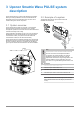
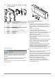
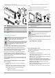
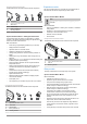
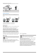
Table Of Contents
- Uponor Smatrix Wave PULSE
- Table of contents
- 1 Copyright and disclaimer
- 2 Preface
- 3 Uponor Smatrix Wave PULSE system description
- 3.1 System overview
- 3.2 Example of a system
- 3.3 Uponor Smatrix Wave PULSE components
- 3.4 Accessories
- 3.5 Functions
- 4 Install Uponor Smatrix Wave PULSE
- 5 Install Uponor Smatrix Wave PULSE room controller
- 5.1 Placement of room controller
- 5.2 Connect optional slave module
- 5.3 Attach room controller to the wall
- 5.4 Install room controller antenna
- 5.5 Install communication module
- 5.6 Connect actuators to room controller
- 5.7 Connect electrical underfloor heating
- 5.8 Connect input to room controller GPI
- 5.9 Connect output to room controller relays
- 5.10 Connect room controller to AC power
- 5.11 Test actuators
- 6 Install Uponor Smatrix Wave room thermostat
- 6.1 Uponor Smatrix Wave T-161
- 6.2 Uponor Smatrix Wave T-163
- 6.6 Uponor Smatrix Wave T-169
- 9 Install Uponor Smatrix Wave relay module
- 9.1 Placement of relay module
- 9.2 Attach relay module to the wall
- 9.3 Connect output to relay module
- 9.4 Register relay module to room controller
- 9.5 Use relay module to connect fan coils
- 9.6 Use relay module for time delayed two stage additional cooling (requires communication module)
- 10 Install another Uponor Smatrix room controller in the system
- 11 Finishing installation
- 12 Operate Uponor Smatrix Wave PULSE room controller
- 12.1 Principle of operation
- 12.2 Normal operation without optional scheduling programs
- 12.3 Operation with scheduling programs
- 12.4 Run mode
- 12.5 Room controller LEDs
- 12.6 Reset the controller
- 12.7 Unregister room controller channels
- 13 Operate Uponor Smatrix PULSE communication module
- 14 Operate Uponor Smatrix Wave thermostats
- 16 Maintenance
- 17 Troubleshooting
- 17.1 General
- Fluctuating floor temperature
- The room is too cold (or too warm in cooling mode)
- Thermostat setpoint is too low
- The temperature displayed on the thermostat changes after the thermostat is moved
- Installation report and room controller/channel numbering on the thermostat label doesn't match
- Installation report and room controller/channel numbering on the thermostatic head label doesn't match
- White indicator cannot be seen in window of an actuator
- Setpoint temperature displayed in the room information menu is lower than the temperature set on the thermostat
- ECO mode
- The room is too warm (or too cold in cooling mode)
- The floor is cold
- All rooms are cold (or warm in cooling mode)
- Disturbing noise from the pump at the same time every week
- No communication
- Communication failure between the room controllers
- 17.2 Troubleshooting after installation
- 17.3 Digital thermostat alarms/problems
- 17.4 Analogue thermostat alarms/problems
- 17.5 Thermostatic head alarms/problems
- The text “bAt” is shown in the display
- The text “POS” is shown in the display
- The display is off
- Radio transmission icon is displayed but the signals are received only when the thermostatic head is close to the antenna
- No radio transmission icon is displayed on thermostatic head screen when buttons are pressed
- 17.6 Communication module alarms/problems
- Alarms shown in Uponor Smatrix PULSE app
- The communication module has lost communication with Uponor cloud services
- The communication module has re-established communication with Uponor cloud services
- Software update failed
- Thermostatic head valve position error
- Floor temperature limit reached
- Faulty temperature sensor
- Faulty external temperature sensor
- Faulty relative humidity sensor
- Faulty Comfort/ECO switch
- Relative humidity sensor limit
- Faulty outdoor temperature sensor
- Faulty heating/cooling supply sensor
- External heating/cooling switch lost
- General systems alarm
- High supply temperature
- Low supply temperature
- Thermostat tamper alarm
- Low average temperature
- Relay module lost
- The communication module does not start
- Bad Wi-Fi connection
- Alarms shown in Uponor Smatrix PULSE app
- 17.7 Room controller alarms/problems
- 17.8 Contact the installer
- 17.9 Installer instructions
- 17.1 General
- 18 Technical data

3 Uponor Smatrix Wave PULSE system
description
Uponor Smatrix Wave is a control system designed for underfloor
heating and cooling installations. Comfort, user friendliness and
temperature control for each individual room of a home can be
combined through the various components.
3.1 System overview
Uponor Smatrix Wave consists of a controller, a communication
module (optional), thermostats, and actuators. The controller
manages the operation of the actuators when the thermostats detect
a demand for heating and/or cooling
System optimization and settings (for up to four room controllers) is
facilitated via the Uponor Smatrix PULSE app (connected via the
communication module). The system can function without the
communication module, but with reduced functionality.
Uponor Smatrix Wave is controlled by different types of thermostats.
Designed for maximum comfort, the thermostats communicate with
the room controller by radio link. It is possible to mix the different
types of Uponor Smatrix Wave thermostats in the same installation.
3.2 Example of a system
The illustration below shows Uponor Smatrix Wave with
installation and thermostats.
CD0000022
B
A
C
D
Note
The floor sensor can be connected to both thermostats
which can be used for floor temperature limitation.
For example, the maximum limitation can protect a
sensitive floor covering from exposure of too high
temperatures when there is a high heating demand. The
minimum limitation can keep a tiled floor warm even
when there is a no general heating demand for the room.
Item Description
A
B
A3800169 Uponor Smatrix Wave T-169,
C
D
A3800161 Uponor Smatrix Wave T-161
Uponor Smatrix Wave PULSE X-265, Page 7 (room controller)
Uponor Smatrix PULSE Com R-208, Page 8
(communication
module)
6
|
Uponor Smatrix Wave PULSE
|
Installation and operation manual
115v
Relay
115v Power Supply
A380265C Uponor Smatrix Pulse Controller X-265
A3801208 Uponor Smatrix Communication Module R-208