
Installation and Operation Manual
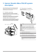
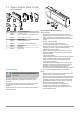
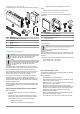
Table Of Contents
- Uponor Smatrix Wave PULSE
- Table of contents
- 1 Copyright and disclaimer
- 2 Preface
- 3 Uponor Smatrix Wave PULSE system description
- 3.1 System overview
- 3.2 Example of a system
- 3.3 Uponor Smatrix Wave PULSE components
- 3.4 Accessories
- 3.5 Functions
- 4 Install Uponor Smatrix Wave PULSE
- 5 Install Uponor Smatrix Wave PULSE room controller
- 5.1 Placement of room controller
- 5.2 Connect optional slave module
- 5.3 Attach room controller to the wall
- 5.4 Install room controller antenna
- 5.5 Install communication module
- 5.6 Connect actuators to room controller
- 5.7 Connect electrical underfloor heating
- 5.8 Connect input to room controller GPI
- 5.9 Connect output to room controller relays
- 5.10 Connect room controller to AC power
- 5.11 Test actuators
- 6 Install Uponor Smatrix Wave room thermostat
- 6.1 Uponor Smatrix Wave T-161
- 6.2 Uponor Smatrix Wave T-163
- 6.6 Uponor Smatrix Wave T-169
- 9 Install Uponor Smatrix Wave relay module
- 9.1 Placement of relay module
- 9.2 Attach relay module to the wall
- 9.3 Connect output to relay module
- 9.4 Register relay module to room controller
- 9.5 Use relay module to connect fan coils
- 9.6 Use relay module for time delayed two stage additional cooling (requires communication module)
- 10 Install another Uponor Smatrix room controller in the system
- 11 Finishing installation
- 12 Operate Uponor Smatrix Wave PULSE room controller
- 12.1 Principle of operation
- 12.2 Normal operation without optional scheduling programs
- 12.3 Operation with scheduling programs
- 12.4 Run mode
- 12.5 Room controller LEDs
- 12.6 Reset the controller
- 12.7 Unregister room controller channels
- 13 Operate Uponor Smatrix PULSE communication module
- 14 Operate Uponor Smatrix Wave thermostats
- 16 Maintenance
- 17 Troubleshooting
- 17.1 General
- Fluctuating floor temperature
- The room is too cold (or too warm in cooling mode)
- Thermostat setpoint is too low
- The temperature displayed on the thermostat changes after the thermostat is moved
- Installation report and room controller/channel numbering on the thermostat label doesn't match
- Installation report and room controller/channel numbering on the thermostatic head label doesn't match
- White indicator cannot be seen in window of an actuator
- Setpoint temperature displayed in the room information menu is lower than the temperature set on the thermostat
- ECO mode
- The room is too warm (or too cold in cooling mode)
- The floor is cold
- All rooms are cold (or warm in cooling mode)
- Disturbing noise from the pump at the same time every week
- No communication
- Communication failure between the room controllers
- 17.2 Troubleshooting after installation
- 17.3 Digital thermostat alarms/problems
- 17.4 Analogue thermostat alarms/problems
- 17.5 Thermostatic head alarms/problems
- The text “bAt” is shown in the display
- The text “POS” is shown in the display
- The display is off
- Radio transmission icon is displayed but the signals are received only when the thermostatic head is close to the antenna
- No radio transmission icon is displayed on thermostatic head screen when buttons are pressed
- 17.6 Communication module alarms/problems
- Alarms shown in Uponor Smatrix PULSE app
- The communication module has lost communication with Uponor cloud services
- The communication module has re-established communication with Uponor cloud services
- Software update failed
- Thermostatic head valve position error
- Floor temperature limit reached
- Faulty temperature sensor
- Faulty external temperature sensor
- Faulty relative humidity sensor
- Faulty Comfort/ECO switch
- Relative humidity sensor limit
- Faulty outdoor temperature sensor
- Faulty heating/cooling supply sensor
- External heating/cooling switch lost
- General systems alarm
- High supply temperature
- Low supply temperature
- Thermostat tamper alarm
- Low average temperature
- Relay module lost
- The communication module does not start
- Bad Wi-Fi connection
- Alarms shown in Uponor Smatrix PULSE app
- 17.7 Room controller alarms/problems
- 17.8 Contact the installer
- 17.9 Installer instructions
- 17.1 General
- 18 Technical data

2 Preface
This installation and operation manual describes how to install and
operate the components of the system.
2.1 Safety instructions
Warnings used in this manual
The following symbols are used in Uponor ducumentation to indicate
special precautions when installing andoperating any Uponor
equipment:
Warning!
Risk of injury. Ignoring warnings can cause injury or
damage components.
Caution!
Ignoring cautions can cause malfunctions.
Note
Important information to the section in the manual.
Safety measures
Conform to the following measures when installing and operating any
Uponor equipment:
• Read and follow the instructions in the installation and operation
manual.
• Installation must be performed by a competent person in
accordance with local regulations.
• It is prohibited to make changes or modifications not specified in
this manual.
• All power supplies must be switched off before starting any
wiring work.
• Do not use water to clean Uponor components.
• Do not expose the Uponor components to flammable vapours or
gases.
Uponor cannot accept any responsibility for damage or breakdown
that can result from ignoring these instructions.
Power
Warning!
The Uponor system uses 115 VAC, 60 Hz power. In
case of emergency, immediately disconnect the
power.
Technical constraints
Caution!
To avoid interference, keep installation/data cables away
from power cables of more than 50 V.
2.2 Limitations for radio
transmission
Wireless Uponor products uses radio transmission for
communication. The frequency used is reserved for similar
applications, and the chances of interference from other radio
sources are very low.
However, in some rare cases, it might not be possible to establish
perfect radio communication. The transmission range is sufficient for
most applications, but each building has different obstacles affecting
radio communication and maximum transmission distance. If
communication difficulties exist, Uponor recommends relocating the
antenna to a more optimal position, and not installing Uponor radio
sources too close to each other (at least 16" / 40cm apart), for
solving exceptional problems.
2.3 Correct disposal of this
product (Waste Electrical and
Electronic Equipment)
This marking shown on the product or its literature indicates
that it should not be disposed with other household wasted at the end
of its working life. To prevent possible harm to the environment or
human health from uncontrolled waste disposal, please separate this
from other types of wastes and recycle it responsibly to promote the
sustainable reuse of material resources.
Household users should contact either the distributor where they
purchased this product, or their local government office, for details of
where and how they can take this item for environmentally safe
recycling.
Business users
should contact their supplier and check the terms and
conditions of the purchase contract. This product should not be mixed
with other commercial wastes of disposal.
Uponor Smatrix Wave PULSE
|
Installation and operation manual
|
5