
Installation and Operation Manual
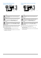
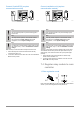
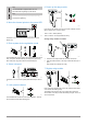
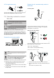
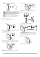
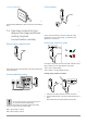
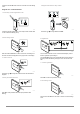
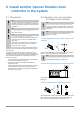
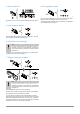
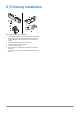
Table Of Contents
- Uponor Smatrix Wave PULSE
- Table of contents
- 1 Copyright and disclaimer
- 2 Preface
- 3 Uponor Smatrix Wave PULSE system description
- 3.1 System overview
- 3.2 Example of a system
- 3.3 Uponor Smatrix Wave PULSE components
- 3.4 Accessories
- 3.5 Functions
- 4 Install Uponor Smatrix Wave PULSE
- 5 Install Uponor Smatrix Wave PULSE room controller
- 5.1 Placement of room controller
- 5.2 Connect optional slave module
- 5.3 Attach room controller to the wall
- 5.4 Install room controller antenna
- 5.5 Install communication module
- 5.6 Connect actuators to room controller
- 5.7 Connect electrical underfloor heating
- 5.8 Connect input to room controller GPI
- 5.9 Connect output to room controller relays
- 5.10 Connect room controller to AC power
- 5.11 Test actuators
- 6 Install Uponor Smatrix Wave room thermostat
- 6.1 Uponor Smatrix Wave T-161
- 6.2 Uponor Smatrix Wave T-163
- 6.6 Uponor Smatrix Wave T-169
- 9 Install Uponor Smatrix Wave relay module
- 9.1 Placement of relay module
- 9.2 Attach relay module to the wall
- 9.3 Connect output to relay module
- 9.4 Register relay module to room controller
- 9.5 Use relay module to connect fan coils
- 9.6 Use relay module for time delayed two stage additional cooling (requires communication module)
- 10 Install another Uponor Smatrix room controller in the system
- 11 Finishing installation
- 12 Operate Uponor Smatrix Wave PULSE room controller
- 12.1 Principle of operation
- 12.2 Normal operation without optional scheduling programs
- 12.3 Operation with scheduling programs
- 12.4 Run mode
- 12.5 Room controller LEDs
- 12.6 Reset the controller
- 12.7 Unregister room controller channels
- 13 Operate Uponor Smatrix PULSE communication module
- 14 Operate Uponor Smatrix Wave thermostats
- 16 Maintenance
- 17 Troubleshooting
- 17.1 General
- Fluctuating floor temperature
- The room is too cold (or too warm in cooling mode)
- Thermostat setpoint is too low
- The temperature displayed on the thermostat changes after the thermostat is moved
- Installation report and room controller/channel numbering on the thermostat label doesn't match
- Installation report and room controller/channel numbering on the thermostatic head label doesn't match
- White indicator cannot be seen in window of an actuator
- Setpoint temperature displayed in the room information menu is lower than the temperature set on the thermostat
- ECO mode
- The room is too warm (or too cold in cooling mode)
- The floor is cold
- All rooms are cold (or warm in cooling mode)
- Disturbing noise from the pump at the same time every week
- No communication
- Communication failure between the room controllers
- 17.2 Troubleshooting after installation
- 17.3 Digital thermostat alarms/problems
- 17.4 Analogue thermostat alarms/problems
- 17.5 Thermostatic head alarms/problems
- The text “bAt” is shown in the display
- The text “POS” is shown in the display
- The display is off
- Radio transmission icon is displayed but the signals are received only when the thermostatic head is close to the antenna
- No radio transmission icon is displayed on thermostatic head screen when buttons are pressed
- 17.6 Communication module alarms/problems
- Alarms shown in Uponor Smatrix PULSE app
- The communication module has lost communication with Uponor cloud services
- The communication module has re-established communication with Uponor cloud services
- Software update failed
- Thermostatic head valve position error
- Floor temperature limit reached
- Faulty temperature sensor
- Faulty external temperature sensor
- Faulty relative humidity sensor
- Faulty Comfort/ECO switch
- Relative humidity sensor limit
- Faulty outdoor temperature sensor
- Faulty heating/cooling supply sensor
- External heating/cooling switch lost
- General systems alarm
- High supply temperature
- Low supply temperature
- Thermostat tamper alarm
- Low average temperature
- Relay module lost
- The communication module does not start
- Bad Wi-Fi connection
- Alarms shown in Uponor Smatrix PULSE app
- 17.7 Room controller alarms/problems
- 17.8 Contact the installer
- 17.9 Installer instructions
- 17.1 General
- 18 Technical data

8. Exit registration mode
3 s
SI0000078
Press and hold the OK button on the room controller until the green
LEDs turn off to end registration and return to run mode.
7.5 Use relay module to connect
fan coils
Caution!
Uponor recommends connecting no more than 4 fancoils
per room controller to maintain the regulating
performance.
Caution!
In rooms with a fan coil, make sure that an actuator is not
connected to the first room channel, as that channel is
used to control the fan coil.
The relay module can be used to control fan coils in a room.
The fan coil is connected to a relay module which is registered to a
room thermostat channel, and is operated depending on settings in
the app (requires communication module). When selecting fan coil in
the cooling setting in the app, select the first room channel to where
the thermostat is registered.
Connect fan coil to relay module
WD0000017
Note
This connection requires dry contact sensing inputs in
the fan coil.
Note
This relay function requires a communication module,
and must be set in Installer settings during initial
configuration, or in the System settings menu.
The system can control one fan coil per thermostat channel. The fan
coil is started and set to a low speed when the relays are closed.
1. Ensure that the power is disconnected from both the relay
module and the ventilation unit.
2. Connect the fan coil speed cable to the connector 1A and 1B on
the relay module.
3. Connect the fan coil on/off cable to the connector 2A and 2B on
the relay module.
Register fan coil connected relay module to
thermostat
Connect power
SI0000044
Connect the power cables from the relay module and cooling
components to a 234 VAC power supply, or if required by
local regulations, to a junction box.
Power up the relay module
1x
2x
SI0000040
Power up the relay module and count the number of flashes of LED 2
(blue) to ensure it is in normal run mode.
LED 2: 1 flash = Normal (default)
LED 2: 2 flashes = Two stage additional cooling
Change relay module run mode
1
2
SI0000041
1. Power down the relay module and wait about 10 seconds.
2.
Press and hold the button on the relay module while turning it on
again.
LED 2 flashes once (Normal run mode).
Uponor Smatrix Wave PULSE
|
Installation and operation manual
|
46
24VAC
24VAC
24VAC
24VAC
X