
Installation and Operation Manual
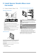
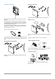
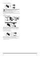
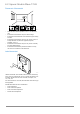
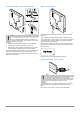
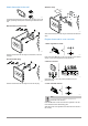
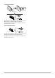

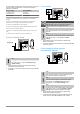
Table Of Contents
- Uponor Smatrix Wave PULSE
- Table of contents
- 1 Copyright and disclaimer
- 2 Preface
- 3 Uponor Smatrix Wave PULSE system description
- 3.1 System overview
- 3.2 Example of a system
- 3.3 Uponor Smatrix Wave PULSE components
- 3.4 Accessories
- 3.5 Functions
- 4 Install Uponor Smatrix Wave PULSE
- 5 Install Uponor Smatrix Wave PULSE room controller
- 5.1 Placement of room controller
- 5.2 Connect optional slave module
- 5.3 Attach room controller to the wall
- 5.4 Install room controller antenna
- 5.5 Install communication module
- 5.6 Connect actuators to room controller
- 5.7 Connect electrical underfloor heating
- 5.8 Connect input to room controller GPI
- 5.9 Connect output to room controller relays
- 5.10 Connect room controller to AC power
- 5.11 Test actuators
- 6 Install Uponor Smatrix Wave room thermostat
- 6.1 Uponor Smatrix Wave T-161
- 6.2 Uponor Smatrix Wave T-163
- 6.6 Uponor Smatrix Wave T-169
- 9 Install Uponor Smatrix Wave relay module
- 9.1 Placement of relay module
- 9.2 Attach relay module to the wall
- 9.3 Connect output to relay module
- 9.4 Register relay module to room controller
- 9.5 Use relay module to connect fan coils
- 9.6 Use relay module for time delayed two stage additional cooling (requires communication module)
- 10 Install another Uponor Smatrix room controller in the system
- 11 Finishing installation
- 12 Operate Uponor Smatrix Wave PULSE room controller
- 12.1 Principle of operation
- 12.2 Normal operation without optional scheduling programs
- 12.3 Operation with scheduling programs
- 12.4 Run mode
- 12.5 Room controller LEDs
- 12.6 Reset the controller
- 12.7 Unregister room controller channels
- 13 Operate Uponor Smatrix PULSE communication module
- 14 Operate Uponor Smatrix Wave thermostats
- 16 Maintenance
- 17 Troubleshooting
- 17.1 General
- Fluctuating floor temperature
- The room is too cold (or too warm in cooling mode)
- Thermostat setpoint is too low
- The temperature displayed on the thermostat changes after the thermostat is moved
- Installation report and room controller/channel numbering on the thermostat label doesn't match
- Installation report and room controller/channel numbering on the thermostatic head label doesn't match
- White indicator cannot be seen in window of an actuator
- Setpoint temperature displayed in the room information menu is lower than the temperature set on the thermostat
- ECO mode
- The room is too warm (or too cold in cooling mode)
- The floor is cold
- All rooms are cold (or warm in cooling mode)
- Disturbing noise from the pump at the same time every week
- No communication
- Communication failure between the room controllers
- 17.2 Troubleshooting after installation
- 17.3 Digital thermostat alarms/problems
- 17.4 Analogue thermostat alarms/problems
- 17.5 Thermostatic head alarms/problems
- The text “bAt” is shown in the display
- The text “POS” is shown in the display
- The display is off
- Radio transmission icon is displayed but the signals are received only when the thermostatic head is close to the antenna
- No radio transmission icon is displayed on thermostatic head screen when buttons are pressed
- 17.6 Communication module alarms/problems
- Alarms shown in Uponor Smatrix PULSE app
- The communication module has lost communication with Uponor cloud services
- The communication module has re-established communication with Uponor cloud services
- Software update failed
- Thermostatic head valve position error
- Floor temperature limit reached
- Faulty temperature sensor
- Faulty external temperature sensor
- Faulty relative humidity sensor
- Faulty Comfort/ECO switch
- Relative humidity sensor limit
- Faulty outdoor temperature sensor
- Faulty heating/cooling supply sensor
- External heating/cooling switch lost
- General systems alarm
- High supply temperature
- Low supply temperature
- Thermostat tamper alarm
- Low average temperature
- Relay module lost
- The communication module does not start
- Bad Wi-Fi connection
- Alarms shown in Uponor Smatrix PULSE app
- 17.7 Room controller alarms/problems
- 17.8 Contact the installer
- 17.9 Installer instructions
- 17.1 General
- 18 Technical data

Connect external sensor to thermostat
1
2
3
SI0000046
Note
For accurate temperature: attach the outdoor sensor to
the north side of the building where it is unlikely to be
exposed to direct sunlight. Do not place it close to doors,
windows, or air outlets.
1. Remove the breakout plastic on the back of the thermostat.
2. Press the push buttons on the connection terminals.
3. While pressing the push buttons, insert the two wires from the
sensor cable (non polarized) into the connection terminal.
The external temperature sensor input can be used for either a floor,
outdoor or remote temperature sensor. Use the software on the
thermostat to select a control mode which corresponds to the use of
the sensor and thermostat.
Start the thermostat
SI0000105
Remove the plastic transportation strip from the battery to start the
thermostat.
The thermostat use a single CR2032 3V button cell lithium battery
which provides about 2 years of battery life, as long as it is positioned
within radio range of the room controller. Ensure that the battery is
correctly inserted in the thermostat.
The thermostat will perform a self test, for about 10 seconds, when
the battery have been inserted. The system will be blocked for input
during this period.
CD0000015
Current software version is displayed during power up.
Select thermostat control mode
SI0000113
Note
If no button on the thermostat is pressed for about
8 seconds, while in a submenu, the current values will be
saved and the software exits to the settings menu. About
about 60 seconds later, it exits to run mode.
If an external sensor is connected to the thermostat, a control mode
must be selected to accommodate the extra functionality of the
sensor.
See 04 Control mode, Page 93, for how to change the setting.
Uponor Smatrix Wave PULSE
|
Installation and operation manual
|
38