
Installation and Operation Manual
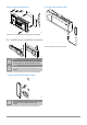
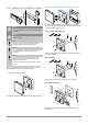
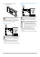
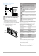
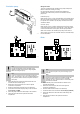
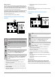
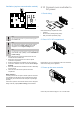
Table Of Contents
- Uponor Smatrix Wave PULSE
- Table of contents
- 1 Copyright and disclaimer
- 2 Preface
- 3 Uponor Smatrix Wave PULSE system description
- 3.1 System overview
- 3.2 Example of a system
- 3.3 Uponor Smatrix Wave PULSE components
- 3.4 Accessories
- 3.5 Functions
- 4 Install Uponor Smatrix Wave PULSE
- 5 Install Uponor Smatrix Wave PULSE room controller
- 5.1 Placement of room controller
- 5.2 Connect optional slave module
- 5.3 Attach room controller to the wall
- 5.4 Install room controller antenna
- 5.5 Install communication module
- 5.6 Connect actuators to room controller
- 5.7 Connect electrical underfloor heating
- 5.8 Connect input to room controller GPI
- 5.9 Connect output to room controller relays
- 5.10 Connect room controller to AC power
- 5.11 Test actuators
- 6 Install Uponor Smatrix Wave room thermostat
- 6.1 Uponor Smatrix Wave T-161
- 6.2 Uponor Smatrix Wave T-163
- 6.6 Uponor Smatrix Wave T-169
- 9 Install Uponor Smatrix Wave relay module
- 9.1 Placement of relay module
- 9.2 Attach relay module to the wall
- 9.3 Connect output to relay module
- 9.4 Register relay module to room controller
- 9.5 Use relay module to connect fan coils
- 9.6 Use relay module for time delayed two stage additional cooling (requires communication module)
- 10 Install another Uponor Smatrix room controller in the system
- 11 Finishing installation
- 12 Operate Uponor Smatrix Wave PULSE room controller
- 12.1 Principle of operation
- 12.2 Normal operation without optional scheduling programs
- 12.3 Operation with scheduling programs
- 12.4 Run mode
- 12.5 Room controller LEDs
- 12.6 Reset the controller
- 12.7 Unregister room controller channels
- 13 Operate Uponor Smatrix PULSE communication module
- 14 Operate Uponor Smatrix Wave thermostats
- 16 Maintenance
- 17 Troubleshooting
- 17.1 General
- Fluctuating floor temperature
- The room is too cold (or too warm in cooling mode)
- Thermostat setpoint is too low
- The temperature displayed on the thermostat changes after the thermostat is moved
- Installation report and room controller/channel numbering on the thermostat label doesn't match
- Installation report and room controller/channel numbering on the thermostatic head label doesn't match
- White indicator cannot be seen in window of an actuator
- Setpoint temperature displayed in the room information menu is lower than the temperature set on the thermostat
- ECO mode
- The room is too warm (or too cold in cooling mode)
- The floor is cold
- All rooms are cold (or warm in cooling mode)
- Disturbing noise from the pump at the same time every week
- No communication
- Communication failure between the room controllers
- 17.2 Troubleshooting after installation
- 17.3 Digital thermostat alarms/problems
- 17.4 Analogue thermostat alarms/problems
- 17.5 Thermostatic head alarms/problems
- The text “bAt” is shown in the display
- The text “POS” is shown in the display
- The display is off
- Radio transmission icon is displayed but the signals are received only when the thermostatic head is close to the antenna
- No radio transmission icon is displayed on thermostatic head screen when buttons are pressed
- 17.6 Communication module alarms/problems
- Alarms shown in Uponor Smatrix PULSE app
- The communication module has lost communication with Uponor cloud services
- The communication module has re-established communication with Uponor cloud services
- Software update failed
- Thermostatic head valve position error
- Floor temperature limit reached
- Faulty temperature sensor
- Faulty external temperature sensor
- Faulty relative humidity sensor
- Faulty Comfort/ECO switch
- Relative humidity sensor limit
- Faulty outdoor temperature sensor
- Faulty heating/cooling supply sensor
- External heating/cooling switch lost
- General systems alarm
- High supply temperature
- Low supply temperature
- Thermostat tamper alarm
- Low average temperature
- Relay module lost
- The communication module does not start
- Bad Wi-Fi connection
- Alarms shown in Uponor Smatrix PULSE app
- 17.7 Room controller alarms/problems
- 17.8 Contact the installer
- 17.9 Installer instructions
- 17.1 General
- 18 Technical data

Relay function
The boiler relay can be used to send a signal to either fire the heat
source, or to power open a 2-port motorised zone valve positioned on
the flow to the underfloor heating manifold. If the relay is used to
power open a zone valve then, the volt free auxiliary contacts on the
zone valve should be used to fire the heat source.
Alternatively, the boiler relay can be used to send a demand signal to
an electrically operated water temperature room controller. The
additional contacts on the water temperature controller should then
be used to fire the heat source.
The boiler is activated when the relay is closed.
Heating/cooling (requires communication
module)
WD0000005
RELAY 2 (BOILER)
Caution!
If more than one room controller is available in the
system, and the circulation pump settings in Installer
settings is set to Common. The connector on the other
room controllers can be used for heating/cooling output
signal.
Note
This connection requires a dry contact sensing input in
the component producing heating/cooling.
Note
This relay function requires a communication module,
and must be set in Installer settings during initial
configuration, or in the System settings menu.
Note
In systems with a communication module, make sure that
room controller
, relay 2 (Boiler), is set to H/C Switch in
Installer settings and that cooling is available in the
system.
1. Ensure that the power is disconnected from both the room
controller and the heating/cooling relay.
2. Remove the screw and open the cover for the optional
connections compartment.
3. Route the cable from/to the heating/cooling relay via a cable
entry.
4. Connect the heating/cooling relay to the connection labelled
Relay 2 (BOILER).
5.
Secure the cable to/from the heating/cooling relay with a cable
clamp in the enclosure.
6. Close and secure the lid to the optional connections
compartment.
Relay function
Heating is activated when the relay is open, and cooling is activated
when the relay is closed.
Dehumidifier (requires communication
module)
WD0000008
RELAY 2 (BOILER)
Note
This connection requires a dry contact sensing input in
the dehumidifier
.
Note
This relay function requires a communication module,
and must be set in Installer settings during initial
configuration, or in the System settings menu.
Note
In systems with a communication module, make sure that
room controller, relay 2 (Boiler), is set to Dehumidifier in
Installer settings.
1. Ensure that the power is disconnected from both the room
controller and the dehumidifier.
2. Remove the screw and open the cover for the optional
connections compartment.
3. Route the cable from/to the dehumidifier via a cable entry.
4. Connect the dehumidifier to the connection labelled Relay 2
(BOILER).
5. Secure the cable to/from the dehumidifier with a cable clamp in
the enclosure.
6. Close and secure the lid to the optional connections
compartment.
Relay function
The dehumidifier starts (relay closed) when the relative humidity
setpoint is reached when in cooling mode. It will stop when the
minimum run time of 30 minutes has finalized and when the relative
humidity has decreased below the defined RH setpoint - differential.
30
|
Uponor Smatrix Wave PULSE
|
Installation and operation manual