
Installation and Operation Manual
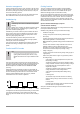
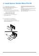
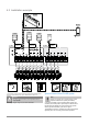
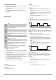
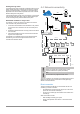
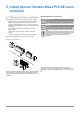
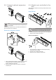
Table Of Contents
- Uponor Smatrix Wave PULSE
- Table of contents
- 1 Copyright and disclaimer
- 2 Preface
- 3 Uponor Smatrix Wave PULSE system description
- 3.1 System overview
- 3.2 Example of a system
- 3.3 Uponor Smatrix Wave PULSE components
- 3.4 Accessories
- 3.5 Functions
- 4 Install Uponor Smatrix Wave PULSE
- 5 Install Uponor Smatrix Wave PULSE room controller
- 5.1 Placement of room controller
- 5.2 Connect optional slave module
- 5.3 Attach room controller to the wall
- 5.4 Install room controller antenna
- 5.5 Install communication module
- 5.6 Connect actuators to room controller
- 5.7 Connect electrical underfloor heating
- 5.8 Connect input to room controller GPI
- 5.9 Connect output to room controller relays
- 5.10 Connect room controller to AC power
- 5.11 Test actuators
- 6 Install Uponor Smatrix Wave room thermostat
- 6.1 Uponor Smatrix Wave T-161
- 6.2 Uponor Smatrix Wave T-163
- 6.6 Uponor Smatrix Wave T-169
- 9 Install Uponor Smatrix Wave relay module
- 9.1 Placement of relay module
- 9.2 Attach relay module to the wall
- 9.3 Connect output to relay module
- 9.4 Register relay module to room controller
- 9.5 Use relay module to connect fan coils
- 9.6 Use relay module for time delayed two stage additional cooling (requires communication module)
- 10 Install another Uponor Smatrix room controller in the system
- 11 Finishing installation
- 12 Operate Uponor Smatrix Wave PULSE room controller
- 12.1 Principle of operation
- 12.2 Normal operation without optional scheduling programs
- 12.3 Operation with scheduling programs
- 12.4 Run mode
- 12.5 Room controller LEDs
- 12.6 Reset the controller
- 12.7 Unregister room controller channels
- 13 Operate Uponor Smatrix PULSE communication module
- 14 Operate Uponor Smatrix Wave thermostats
- 16 Maintenance
- 17 Troubleshooting
- 17.1 General
- Fluctuating floor temperature
- The room is too cold (or too warm in cooling mode)
- Thermostat setpoint is too low
- The temperature displayed on the thermostat changes after the thermostat is moved
- Installation report and room controller/channel numbering on the thermostat label doesn't match
- Installation report and room controller/channel numbering on the thermostatic head label doesn't match
- White indicator cannot be seen in window of an actuator
- Setpoint temperature displayed in the room information menu is lower than the temperature set on the thermostat
- ECO mode
- The room is too warm (or too cold in cooling mode)
- The floor is cold
- All rooms are cold (or warm in cooling mode)
- Disturbing noise from the pump at the same time every week
- No communication
- Communication failure between the room controllers
- 17.2 Troubleshooting after installation
- 17.3 Digital thermostat alarms/problems
- 17.4 Analogue thermostat alarms/problems
- 17.5 Thermostatic head alarms/problems
- The text “bAt” is shown in the display
- The text “POS” is shown in the display
- The display is off
- Radio transmission icon is displayed but the signals are received only when the thermostatic head is close to the antenna
- No radio transmission icon is displayed on thermostatic head screen when buttons are pressed
- 17.6 Communication module alarms/problems
- Alarms shown in Uponor Smatrix PULSE app
- The communication module has lost communication with Uponor cloud services
- The communication module has re-established communication with Uponor cloud services
- Software update failed
- Thermostatic head valve position error
- Floor temperature limit reached
- Faulty temperature sensor
- Faulty external temperature sensor
- Faulty relative humidity sensor
- Faulty Comfort/ECO switch
- Relative humidity sensor limit
- Faulty outdoor temperature sensor
- Faulty heating/cooling supply sensor
- External heating/cooling switch lost
- General systems alarm
- High supply temperature
- Low supply temperature
- Thermostat tamper alarm
- Low average temperature
- Relay module lost
- The communication module does not start
- Bad Wi-Fi connection
- Alarms shown in Uponor Smatrix PULSE app
- 17.7 Room controller alarms/problems
- 17.8 Contact the installer
- 17.9 Installer instructions
- 17.1 General
- 18 Technical data

5 Install Uponor Smatrix Wave PULSE room
controller
5.1 Placement of room controller
Use the following guidelines when positioning the room controller:
• Position the room controller close to the manifold, just above if
possible, and each manifold pair must have its own room
controller. Check the position of the 115 V AC wall socket, or if
required by local regulations, to a junction box, connected to the
mains power.
• Check that the room controller is protected from running or
dripping water.
• Check that the cover of the room controller can be easily
removed.
• Check that connectors and switches are easily accessible.
See Prepare for installation, Page 16, for more information.
Modular placement
B
A
SI0000064
The room controller is designed with the option of modular placement
in mind. This means that all major parts are detachable and can be
placed separately (some extra wiring may be required depending on
placement).
Attaching/detaching components
Caution!
The transformer module is heavy and might detach if the
room controller is held upside down without the cover on.
Caution!
The slave module must be attached by snapping it into
place due to connection pins sticking out of the module.
Note
Wires between transformer and room controller card
needs to be disconnected prior to detaching the
transformer
.
The components can either snap on or off without the need of
removing the covers (A, recommended to do on a flat surface or on a
DIN-rail), or by sliding them into place when the covers are removed
(B).
Uponor Smatrix Wave PULSE
|
Installation and operation manual
|
21