
User Guide

62 l uponorengineering.com
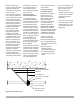
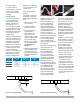
Expansion arm
The exible arm should
be long enough to prevent
damage, and support clamps
should be placed far enough
from the wall to allow for
longitudinal thermal expansion
(see Figure 5-8).
Use the formula below to
calculate the minimum length
of the expansion arm: LB = C
x SQRT(D x ΔL)
Where:
• L is total distance of piping
run from a xed anchor point
to a corner, or in the case of
an expansion loop, from a
xed anchor point to a xed
anchor point.
• LB is the exible arm in
inches.
• C is the material constant
(12 for PEX).
• D is the outside diameter of
the piping.
• ΔL is the thermal-expansion
length in inches.
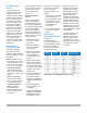
Expansion arm example:
Uponor AquaPEX piping with
an outside diameter of 1.625"
is installed running a length of
75 ft. The hot water it carries is
120ºF/48.9ºC, and the ambient
temperature is 60ºF/15.6ºC.
Calculate the length of the
exible arm. PEX piping
expands at a rate of 1.1" per
10°F temperature change per
100 ft. of piping (27.94mm per
5.56°C temperature change
per 30.48m of piping).
LB = C x √(D x ΔL)
LB= 12 x √(1.625" x (1.1" x
(60/10)/(100 ft./ L))))
LB = 12 x √(1.625" x 4.95")
LB = 12 x 2.84"
LB = 34.08"
The required arm length (LB)
is 34.08" to prevent excessive
stress on the ttings and
support clamps.
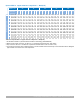
For a list of calculated
exible arm lengths, refer
to Appendix E.
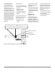
Expansion loop
The same equation applies for
an expansion loop. However,
the arm length (LB) must be
divided into three sections
using the following formula:
LB = 5L1
Expansion loop example:
5L1 = 34.08"
L1 = 34.08/5
L1 = 6.82"
L2 = 2 L1
L2 = 13.63"
For a list of calculated
expansion loop legs, refer to
Appendix E.
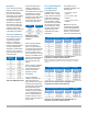
Thermal expansion in
underground applications
For direct-burial applications,
mitigate the effects of thermal
expansion by incorporating
proper installation techniques
that provide adequate
resistance to axial stress.
Per PPI TR-21 Thermal
Expansion and Contraction
in Plastic Piping Systems, a
buried or concrete-encased
pipe is effectively restrained
against both lateral and axial
movement by surrounding
embedment material. The
magnitude of the frictional
restraining force is dependent
on the nature of the soil and
on installation and operating
conditions. For example, the
extent of compaction near the
pipe can affect the quality of
contact between the pipe and
surrounding soil.
The anchoring or restraining
effect of surrounding soil
on pipe movement can be
signicantly augmented
by external pipe geometry.
Tees, lateral connections
and changes in direction all
help to anchor a pipe in the
surrounding soil.
Because the friction between
the pipe and surrounding
material is generally sufcient
to arrest axial pipe movement,
a buried pipe that is subject
to typical uctuations in the
temperature of the uid it
conveys or of the soil that
surrounds it is only subject to
modest axial thermal stresses
that are well within the strength
capabilities of the pipe.
The magnitude of the soil
restraint, which acts on plastic
pipe with an externally smooth
wall, may be estimated from
the following equation:
f = μ • N
Where:
f = Axial frictional resistance
(lbs./inch of pipe length)
μ = Approximate coefcient
of friction between soil and
pipe and between concrete
and pipe. A value of 0.1 is
generally accepted as a
conservative representation
for the case where smooth-
surface plastic pipe makes full
contact with the embedment
material.
N = Normal soil pressure
acting on 1" of width pipe
(psi/inch)
N = π • D
o
• Soil pressure,
where D
o
is the pipe outside
diameter (inches)
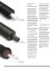
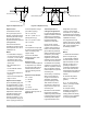
An example of taking
advantage of soil restraint
is installing the piping in a
snaking pattern and utilizing
continuous runs to capitalize
on the piping’s exibility.
Fixed anchor point
Fixed anchor point
L2
L2
L1
L
∆L/2 ∆L/2
Fixed anchor point
Fixed anchor point
LB
L ∆L
Figure 5-8: Expansion arm
Figure 5-9: Expansion loop