
User Guide

38 l uponorengineering.com
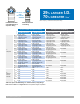
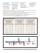
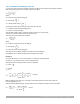
Figure 4-3: System parameters
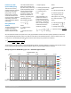
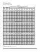
Step three
Develop water size charts for
each pipe material and water
temperature. (See Figures 4-3
and 4-4.)
Designer must know the
following:
• Pipe materials being
designed and range of
sizes for each system
• Supply and return design
water temperatures
Note: For commercial
systems, size domestic
hot-water return piping
per the requirements
stated in ASPE Plumbing
Engineering Design
Handbook, Volume 2,
Plumbing Systems
• Maximum velocity of each
pipe material per water
temperature
• Table approved by the local
authority having jurisdiction
(AHJ) or referenced
plumbing code table for
converting gallons per minute
(gpm) to water supply xture
units (WSFU)
• If the domestic cold-
water system demand is
predominately ush valve or
ush tank WSFU
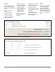
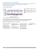
Step four
Apply the appropriate water
size chart to the plumbing
design. Calculate WSFU
demand per pipe segment by
adding all the WSFUs of the
xtures being supplied by that
pipe segment. (See Figure
4-5.)
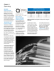
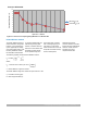
Figure 4-2: Determine the friction loss per foot (or per 100 feet) of pipe