
User Guide

Plumbing Design Assistance Manual l Chapter 4 – Pipe sizing l 37
U.S. pipe sizing
For sizing an Uponor
AquaPEX plumbing system
in residential and light
commercial buildings in the
U.S., use the xture unit
tables for determining pipe
size as published in the model
plumbing codes.
To support this pipe sizing
practice, Uponor consulted
with the International Code
Council (ICC) and the
International Association of
Plumbing and Mechanical
Ofcials (IAPMO) by means
of an evaluation report (ER) to
substantiate their approvals.
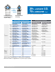
The following ER numbers
endorse the use of the 2012
UPC Table 610.4 (see page
44) (or 2009-prior UPC Table
6-6) and 2015-prior IPC Table
E201.1 (see pages 45-46)
for pipe sizing an Uponor
AquaPEX plumbing system.
• IAPMO ER-0253
• ICC ES PMG 1006
Canada pipe sizing
For sizing an Uponor
AquaPEX plumbing system
in residential high-rise and
small commercial buildings
in Canada, use Table
A-2.6.3.1.(2)A (see page 47)
and other applicable sections
within the 2015 National
Plumbing Code of Canada
(NPCC).
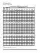
Uniform friction
loss method
For larger systems, the
most common method of pipe
sizing is the uniform friction
loss method. This method
utilizes the pipe material’s
specic ow characteristics
in conjunction with velocity
sizing criteria (see
Appendix B for Uponor
PEX friction loss tables).
The following examples
illustrate how to employ the
uniform friction loss method.
To simplify the uniform
friction loss method when
sizing an Uponor AquaPEX
plumbing system, use
Uponor’s pipe sizing calculator
at uponorpro.com/calculator.
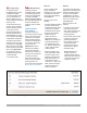
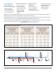
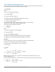
Step one
Perform a building water
supply calculation to
determine how much pressure
is available for friction loss
through the pipe and ttings.
(See Figure 4-1.)
Designer must know the
following:
• Pressure available at building
(minimum static pressure
available before water meter
or after hydro-pneumatic
tank/booster-pump system)
• Minimum xture working
pressure (minimum
pressure required at
farthest xture outlet)
Note: Be sure to select the
most demanding xture in
the farthest xture group
(i.e., bathtub). Refer to local
code for minimum xture
working pressure.
• Static loss (height in feet
of the highest xture outlet
above the supply source)
• Additional component loss
(total pressure loss in psi
of the following system
components — water meter,
lters, softeners, backow
prevention devices and
pressure regulators)
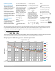
Step two
Calculate the total developed
length (TDL) of the system and
divide the available pressure
for friction loss (calculated
in Figure 4-1) by the TDL to
determine the friction loss per
foot or per 100 feet of pipe.
(See Figure 4-2.)
Designer must know the
following:
• Longest run to xture (total
linear feet of piping from
water meter or supply source
to the most hydraulically
demanding xture)
• Fitting allowance (percentage
of longest run piping that
represents friction loss
through ttings and valves
along the critical path,
typically between 20 and
50 percent for an Uponor
AquaPEX system)
Note: Alternatively, the
designer can add up
equivalent-length losses of
ttings and valves along the
critical path and add to the
longest run footage.
Figure 4-1: Building water supply calculation