Plumbing Design Assistance Manual (PDAM)
Plumbing Design Assistance Manual is published by Uponor Inc. 5925 148th Street West Apple Valley, MN 55124 USA T 800.321.4739 F 952.891.2008 Uponor Ltd. 6510 Kennedy Road Mississauga, ON L5T 2X4 CANADA T 888.994.7726 F 800.638.9517 uponorpro.com uponorengineering.com © 2017 Uponor All rights reserved. Fourth Edition First printing March 2008 Printed in the United States of America Uponor has used reasonable efforts in collecting, preparing and providing quality information and material in this manual.
Table of Contents Plumbing Design Assistance Manual Foreword . . . . . . . . . . . . . . . . . . . . . . . . . . . . . . . . . . . . . . . . . . . . . . . . . . . . . . . . . . . . . . . . iv Chapter 1: Uponor PEX properties . . . . . . . . . . . . . . . . . . . . . . . . . . . . . . . . . . . . . . . . . . . . . . . . . . 1 Uponor PEX properties . . . . . . . . . . . . . . . .
ASTM E814 and CAN/ULC-S115 listings . . . . . . . . . . . . . . . . . . . . . . . . . . . . . . . . . . . . . . . . . . . . . .27 Cast-in-place sleeves . . . . . . . . . . . . . . . . . . . . . . . . . . . . . . . . . . . . . . . . . . . . . . . . . . . . . . . . 28 ASTM E84 — surface burning characteristics . . . . . . . . . . . . . . . . . . . . . . . . . . . . . . . . . .
Reforming kinked piping . . . . . . . . . . . . . . . . . . . . . . . . . . . . . . . . . . . . . . . . . . . . . . . . . . . . . . .64 Thawing frozen piping . . . . . . . . . . . . . . . . . . . . . . . . . . . . . . . . . . . . . . . . . . . . . . . . . . . . . . . .64 Supporting Uponor PEX pipe . . . . . . . . . . . . . . . . . . . . . . . . . . . . . . . . . .
Foreword This design assistance manual is published for architects, building officials, engineers and mechanical contractors interested in Uponor professional plumbing systems. It describes general installation recommendations that use Uponor AquaPEX® piping products. Refer to local codes for additional requirements. iv l uponorengineering.com Uponor made reasonable efforts to collect, prepare and provide quality information and material in this manual.
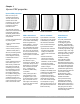
Chapter 1: Uponor PEX properties Uponor PEX properties PEX is an acronym for crosslinked polyethylene. The “PE” refers to the raw material used to make polyethylene; the “X” refers to the crosslinking of the polyethylene across its molecular chains. The molecular chains are linked into a three-dimensional network that makes PEX remarkably durable within a wide range of temperatures and pressures. Currently, three methods exist for producing PEX.
Ultraviolet (UV) resistance The test method for evaluating UV resistance as required by ASTM F876 is ASTM F2657 Test Method for Outdoor Weathering Exposure of Cross-linked Polyethylene (PEX). According to ASTM F876, PEX piping must bear a four-digit code to signify the requirements it meets. The second digit in the code references the minimum ultraviolet (UV) resistance of the piping.
Hydrostatic temperature and pressure ratings Interpolation method Through scientific research and historical experience, hydrostatic design basis (HDB) ratings have been shown to be useful indicators of relative long-term strength of thermoplastic materials when tested under the conditions specified in test method ASTM D2837. The HDB is used to determine the temperature and pressure ratings of a specific material. These temperature and pressure ratings are based on an extrapolated life of 50 years.
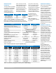
Standards, codes and listings Uponor AquaPEX piping is manufactured to meet the following requirements.
ProPEX® fittings Uponor ProPEX® fittings are available in both EP and LF brass and are tested and listed to: • ASTM F1960 Standard Specification for Cold Expansion Fittings with PEX Reinforcing Rings for Use With Cross-linked Polyethylene (PEX) Piping • CAN/CSA B137.
The strength of Uponor EP Uponor EP is made from UDEL® polysulfone, Radel R® polyphenylsulfone or Acudel® modified polyphenylsulfone. These materials are part of a family of polymers that have been used successfully in the demanding environments of medical appliance, aerospace and plumbing for many years. In fact, lab tests prove the Uponor 2" ProPEX EP Tee and ProPEX connection are able to withstand up to 2,900 lbs. of pull force without failure.
Chapter 2: Making ProPEX connections Uponor ProPEX ASTM F1960 (CAN/CSA B137.5) cold-expansion fittings make solid, permanent, manufactured connections without the need for torches, glues, solder, flux or gauges. The unique shape memory of Uponor PEX piping forms a tight seal around the fitting, creating a strong, reliable connection. This document shows how to make proper ProPEX connections using one of the following tools.
Making ProPEX connections with Milwaukee M12 or M18 ProPEX expansion tools Note: All standard Uponor expander heads are compatible with the M12 and M18 tools. Uponor expander heads will not auto-rotate on the Milwaukee tools (only Milwaukee expansion heads will auto-rotate on the M12 and M18). H-heads are not compatible with Milwaukee tools and Milwaukee heads are not compatible with Uponor tools. Milwaukee heads are easily distinguished by color coding and the Milwaukee logo.
6a 6b 6c Shoulder ProPEX coupling Insert ProPEX fitting into ½" Uponor PEX piping. 6d 6e Shoulder Insert ProPEX fitting into 1" Uponor PEX piping. 6. After the final expansion, immediately remove the tool and insert the fitting. Ensure the piping and ring seat against the shoulder of the fitting. Important! Only perform the necessary number of expansions. DO NOT over expand the pipe. You should feel some resistance as the fitting goes into the piping.
Making ProPEX connections with Milwaukee M18 FORCELOGIC ProPEX expansion tools FORCELOGIC expansion head installation The Milwaukee FORCELOGIC ProPEX Expansion Tool for 2", 2½" and 3" Uponor PEX pipe features an auto-rotating head with specially designed alignment cogs. This requires slightly different head installation than the M12 and M18 ProPEX expansion tools for ⅜" to 1½" pipe sizes. 1. Remove the battery pack and place the FORCELOGIC tool in the upright position (cone up). 2.
Making a ProPEX connection 1. S quare cut the PEX piping perpendicular to the length of the piping. Remove all excess material or burs that might affect the fitting connection. 2. Slide the ProPEX ring over the end of the piping until it reaches the stop edge. 3. The Milwaukee tool comes with built-in auto rotation, meaning the head will automatically rotate to ensure the piping is evenly expanded. 1 Note: To cancel the expansion process quickly, pull and release the trigger. 4.
Making ProPEX connections with ProPEX 201 corded expander tools 1. S quare cut the PEX piping perpendicular to the length of the piping. Remove all excess material or burrs that might affect the fitting connection. 2. S lide the ProPEX ring over the end of the piping until it reaches the stop edge. If using a ProPEX ring without a stop edge, extend the ring over the end of the piping no more than 1⁄16" (1mm). 3. Slide the expander head into the piping until it stops.
5. R elease the trigger, remove the head from the piping, rotate it ⅛ turn and slide the head back into the piping. Continue expanding and rotating until the piping and ring are snug against the shoulder on the expander head. See Table 2-2. Important! Rotating the tool between expansions will provide smooth, even expansion of the piping. Failure to rotate the tool will cause deep grooves in the piping which can result in potential leak paths. 6.
Making ⅜" ProPEX connections Proper expander tool and head maintenance When making a ⅜" ProPEX connection, expand the ring once on each side to properly fit over the piping. Refer to the following instructions to make a ⅜" ProPEX connection. • Use a lint-free cloth to apply a light coat of lubricant to the cone prior to making any ProPEX connections. 1. S quare cut the PEX piping perpendicular to the length of the piping. Remove all excess material or burrs that might affect the fitting connection. 2.
Disconnecting a ProPEX brass fitting 2 ProPEX brass and EP fittings are manufactured connections that can be concealed in walls, ceilings and floors. When necessary, ProPEX brass fittings can be disconnected. Important! EP fittings cannot be reclaimed. Refer to the following guidelines for disconnecting a ProPEX brass fitting. 3 1. E nsure the system is not pressurized. 2. U se a utility knife to carefully cut through the ProPEX ring. Important! Do not heat the ring prior to cutting it.
Troubleshooting ProPEX connections Trouble-free ProPEX installations begin with a tool that is maintained in proper working condition. If the tool or segment fingers are damaged, it is very difficult to make a proper connection. Refer to the following guidelines to assist with challenges in the field. Fittings won’t seal • Make sure the expander head is securely tightened onto the tool. • Ensure the segment fingers are not bent.
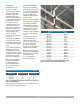
Chapter 3: Fire-resistant construction Wood-frame wall assemblies Assembly numbers Building elements ITS Design No. UW/WA 60-02 Wood-frame wall assemblies complying with ASTM E119 and CAN/ULC-S101 have the following requirements. • 1-hour • Joists: Nominal 2x10 solid sawn wood, open-web wood or wood I-joist (10" to 24" depth) installed at 24" o.c. maximum Building elements • 1-hour • Studs: Nominal wood 2x4 spaced 16" on center (o.c.
Steel/concrete wall assemblies Steel/concrete wall assemblies complying with ASTM E119 and CAN/ULC-S101 have the following requirements. Assembly numbers Pipe and fittings Assembly numbers QAI Design No. P321-1A • Pipe: Maximum volume of Uponor PEX pipe is 14 cubic inches per 1 cubic foot (8101 cubic centimeters per 1 cubic meter). Approved Uponor PEX pipes include: ITS Design No. UW/FCA 120-01 • 1-hour • Up to 4" PEX QAI Design No.
Wood-frame assemblies (U.S.) Multiport tee detail Wood-frame floor/ceiling assembly (UL Design No. L557/QAI Design No. P321-1F) Wood-stud wall assembly (UL Design No. U372/QAI Design No. P321-1B) Maximum density of Uponor PEX pipe is 4.85 lbs. per linear feet (7.23 kg/m) of cavity • Uponor AquaPEX (up to 3") • Wirsbo hePEX (up to 4") Restricted load-bearing wood stud and gypsum wall assembly Maximum density of Uponor ProPEX EP fittings is 3.33 lbs. (1.
Fixture detail 1 Wood-frame floor/ceiling assembly (UL Design No. L557/QAI Design No. P321-1F) Wood-stud wall assembly (UL Design No. U372/QAI Design No.
Wood-frame assemblies (Canada) Multiport tee detail Wood-frame floor/ceiling assembly (ITS Design No. UW/FCA 60-01/QAI Design No. P321-1F) Wood-stud wall assembly (ITS Design No. UW/WA 60-02/QAI Design No. P321-1B) Maximum density of Uponor PEX pipe is 4.85 lbs. per linear feet (7.23 kg/m) of cavity Restricted load-bearing wood stud and gypsum wall assembly Maximum density of Uponor ProPEX EP fittings is 3.33 lbs. (1.
Fixture detail 1 Wood-frame floor/ceiling assembly (ITS Design No. UW/FCA 60-01/QAI Design No. P321-1F) Wood-stud wall assembly (ITS Design No. UW/WA 60-02/QAI Design No.
Concrete assemblies (U.S.) Multiport tee detail Concrete floor/ceiling assembly (UL Design No. K913/QAI Design No. P321-1D) Steel-stud wall assembly (UL Design No. V444/QAI Design No. P321-1A) Non load-bearing steel stud and gypsum wall assembly • Uponor AquaPEX (up to 3") • Wirsbo hePEX (up to 4") • Pre-insulated Uponor AquaPEX (up to 2" pipe with 2" thick insulation) Maximum density of Uponor PEX pipe is 4.85 lbs per linear feet (7.
Concrete assemblies (Canada) Multiport tee detail Concrete floor/ceiling assembly (ITS design no. UW/FCA 120-02/QAI design no. P321-1D) Steel-stud wall assembly (ITS design no. UW/WA 60-01/QAI design no.
ASTM E814 or CAN/ULC-S115 Combustible and noncombustible pipes penetrating a wall or floor/ceiling fire-rated assembly must include a code-compliant means of passive fire protection. The function of a passive fire protection system, such as firestopping, is to contain the fire within the area in which it started by preventing the products of combustion (smoke, hot gasses and flames) from spreading throughout the structure.
q WL2547 3M™ Fire Barrier Sealant CP 25WB+ 1, 2 3M™ Fire Barrier Sealant IC 15WB+ 3M™ Fire Barrier Water tight Sealant 3000 WT UL Max 2" SDR 9 PEX (closed only). U300, U400, or V400 series gypsum wallboard assemblies. Max. diameter of opening 1½" larger than OD of penetrant. Point contact to max. 1½" annular space. Concentric or eccentric installations. 1 & 2 hour F rating. No mineral wool required.
ASTM E814 and CAN/ULC-S115 listings = ASTM E814 and CAN/ULC-S115 = ASTM E814 only Manufacturer Assembly types 3M™ Wall 1-hour Floor/clg Hilti ® Wall Floor/clg Wall Floor/clg STI Wall Floor/clg PHV-120-04 F-C-2039 W-L-2186 F-C-2081 W-L-2342 F-C-2298 F-C-2319 F-C-2032 PHV-120-11 F-C-2240 W-L-2235 F-C-2230 W-L-2262 F-C-8015 W-L-2100 F-C-2252 W-L-2091 F-C-2343 W-L-2466 F-C-2310 W-L-2373 F-C-2329 W-L-2144 F-C-2319 W-L-2146 F-C-2344 W-L-2474 F-C-2334 W-L-2430 F-C-2212 W
ASTM E814 and CAN/ULC-S115 listings = ASTM E814 and CAN/ULC-S115 Assembly types = ASTM E814 only Manufacturer 3M™ Wall Floor/clg Hilti® Wall Floor/clg Concrete assemblies 1-hour 2-hour RectorSeal® Wall Floor/clg STI Wall Floor/clg HOLDRITE Floor/clg C-AJ-2605 C-AJ-2605 C-AJ-2510 C-AJ-2510 C-AJ-2170 C-AJ-2170 W-J-2162 C-AJ-2628 W-J-2021 C-AJ-2031 F-A-2188 C-AJ-2536 C-AJ-2536 C-AJ-2407 C-AJ-2407 W-J-2122 F-A-2171 W-J-2043 C-AJ-2140 F-A-2221 PHV-120-04 F-A-2115 C-AJ-2647 C-
ASTM E84 — surface burning characteristics As defined by the International Building Code (IBC), combustible piping may be installed in areas required to be of noncombustible construction, provided the piping is installed in a wall or concrete-floor slab or the pipe has a flame-spread (FS) index rating of not more than 25 and a smoke-developed (SD) index rating of not more than 50 when tested in accordance with ASTM E84.
United States — ASTM E84 Minimum 18" Clamp ½" through ¾" Uponor PEX pipe Figure 3-18: QAI P321-1 Guidelines: ½" through ¾" (uninsulated) Limitations: Adjacent runs shall be located at least 18" apart. Clamp No limitation Minimum ½" 25/50 rated insulation ½" through 3" Uponor PEX pipe Figure 3-19: QAI P321-1 Guidelines: ½" through 3" (uninsulated) Limitations: ½" minimum thickness insulation as specified in Table 3-3.
CAN/ ULC-S102.2 — surface burning characteristics As defined by the National Building Code of Canada (NBCC), combustible piping may be installed in areas required to be of noncombustible construction, provided the piping is installed in a wall or concrete-floor slab or the pipe has a flame-spread (FS) index rating of not more than 25 and a smokedeveloped (SD) index rating of not more than 50 when tested in accordance with CAN/ULC-S102.2.
Canada — CAN/ULC-S102.2 No limitation Clamp ½" Uponor PEX pipe (uninsulated) Figure 3-21: QAI P321-1 Guidelines: ½" (uninsulated) Limitations: No spacing limitations. Minimum 18" Clamp ¾" and 1" Uponor PEX pipe (uninsulated) Figure 3-22: QAI P321-1 Guidelines: ¾" and 1" (uninsulated) Limitations: Adjacent pipe runs shall be located at least 18" apart.
Canada — CAN/ULC-S102.
Underwriters Laboratories (UL) 2846 Until recently, piping materials were to be tested under the ASTM E84 method, which was originally developed to test building construction components. The UL 2846 test method was developed specifically for plastic piping materials to test flame and smoke development. Uponor PEX piping (up to 4") carries the UL 2846 Standard for Fire Test of Plastic Water Distribution Plumbing Pipe for Visible Flame and Smoke Characteristics.
Chapter 4: Pipe sizing s Standard dimension ratio Standard dimension ratio (SDR) is a term used in describing the size of PEX piping — it is the conceptual equivalent of a pipe schedule. Dimension ratio (DR) is the average outside diameter (OD) of PEX piping divided by its minimum wall thickness. Temperature and pressure ratings Temperature and pressure ratings for PEX piping are determined by the Plastics Pipe Institute (PPI) as required by the ASTM F876 standard.
B 29% LARGER I.D. 70% GREATER flow B A-F low path B - Internal diameter 1 When comparing 1" F1960 EP with F2159 plastic fittings. 1 ProPEX ASTM F1960 and CAN/CSA B137.5 expansion fitting 8 D 6 7 5 ASTM F1807/F2159 insert fitting 4 3x P1110502-AA 3 2 "Date Code" "Supplier ID" 2.3 REF D "Country of Origin" Uponor ProPEX cold-expansion fitting ASTM F1960 brass 2x R.050 BACK SIDE MARKINGS DETAIL ¾" 0.278 sq. inches 6.9 gpm @ 8 ft./sec. 10.4 gpm @ 12 ft./sec. 0.273 sq. inches 6.
U.S. pipe sizing For sizing an Uponor AquaPEX plumbing system in residential and light commercial buildings in the U.S., use the fixture unit tables for determining pipe size as published in the model plumbing codes. To support this pipe sizing practice, Uponor consulted with the International Code Council (ICC) and the International Association of Plumbing and Mechanical Officials (IAPMO) by means of an evaluation report (ER) to substantiate their approvals.
Designer must know the following: ote: For commercial N systems, size domestic hot-water return piping per the requirements stated in ASPE Plumbing Engineering Design Handbook, Volume 2, Plumbing Systems • Pipe materials being designed and range of sizes for each system • Maximum velocity of each pipe material per water temperature Step three Develop water size charts for each pipe material and water temperature. (See Figures 4-3 and 4-4.
Uponor AquaPEX design parameters Domestic hot-water piping Domestic cold-water piping • Maximum velocity of 12 ft./sec. through pipe • Maximum velocity of 12 ft./sec. through pipe • Recommended velocity of 8 ft./sec. through pipe • Maximum operating temperature of 200°F (93.3°C) • Recommended velocity of 10 ft./sec. through pipe Domestic hot-water return piping • Sized per the requirements stated in ASPE Plumbing Engineering Design Handbook, Volume 2, Plumbing Systems • Maximum velocity of 2 ft.
Friction loss with Uponor PEX piping This method relates friction in piping to the roughness of the pipe, fluid velocity, fluid density (water temperature) and fluid viscosity without leveraging correction factors. This is the same for systems using different concentrations of fluids (e.g., propylene glycol). There are two commonly accepted methods to calculate head loss or friction loss in piping systems.
Pressure differential 10 Pressure differential — ft. 9 8 7 6 5 NSF test 4 Calculated 3 P (ft) P (ft) 2 1 0 0.25 0.50 0.75 1.00 1.25 1.50 1.75 2.00 2.25 2.50 2.75 3.00 Pipe size — nominal Figure 4-7: Friction loss comparing Darcy-Weisbach vs. NSF test data Hazen-Williams method The Hazen-Williams method is another method for sizing PEX. However, it is not preferred by Uponor (especially for heating and cooling system sizing).
Comparing Darcy-Weisbach and Hazen-Williams NSF performed testing to calculate the friction loss of Uponor PEX pipe and Uponor ProPEX fittings. The testing allowed Uponor to analyze empirical test data and compare it with the Darcy-Weisbach and Hazen-Williams methods. The following graph illustrates the comparison.
The Cv method for calculating friction loss Cv is a function of flow rate versus pressure drop across the fitting. It also accounts for the density of the fluid. Refer to the following friction loss calculation using the Cv method. ( )( ) Pƒ ∆P = –––– Pw Where, F –––– Cv 2 ∆P = pressure drop across the fitting (psi) ( ) lb Pƒ = fluid density ––– – ft 3 ( ) lb –––– ft The density of water at 60°F (15.6°C) is 62.38 pounds per cubic foot.
UPC table 610.4 WaTer SuPPlY and diSTribuTion Tables taken from IAPMO ER 0253 Table 610.
IPC table E201.
IPC table E201.1 Tables taken from ICC-ES-PMG 1006 46 l uponorengineering.
NPCC table A-2.6.3.1(2)A Tables taken from NPCC Addition of 3.65 m/s (12 fps) flow velocity to Table A-2.6.3.1.(2)A of the National Plumbing Code of Canada, 2010 Water Service Water Distribution Pipe Size Pipe Size in. in. Pressure Range 3/4 1/2 3/4 5/8 3/4 3/4 1 1 1‐1/2 1‐1/4 1‐1/2 1‐1/2 2 1‐1/2 2 2 2‐1/2 2‐1/2 Water Water Service Pipe Distribution Size Pipe Size Water in. in. Service Water Pressure Range Pipe Distribution 3/4 1/2Size Size Pipe 3/4 5/8 in. in.
2) Potable water systems shall be designed, fabricated and installed in accordance with good engineering practice, such as that described in the ASHRAE Handbooks and ASPE Data Books. (See Appendix A.) 3) In one- and two-family dwelling units and manufactured homes, multi-purpose NPCC table 2.6.3.
NPCC 2.6.3.2. table 2.6.3.2 Division B Reproduced with the permission of the National Research Council of Canada, copyright holder. Table 2.6.3.2.A. (Continued) Minimum Size of Supply Pipe, inches Fixture or Device Private Use Hydraulic Load, fixture units Public Use Hydraulic Load, fixture units Cold Hot Total Cold Hot Total Sink, kitchen domestic, greater than 8.3 LPM 3 ⁄8 1.5 1.5 2 1.5 1.5 2 Sink, laboratory 3 ⁄8 - - - 1.5 1.
Division B 2.6.3.2. NPCC table 2.6.3.2 Table 2.6.3.2.C. of Water Systems for Water Closets with Direct Reproduced with the Sizing permission of theDistribution National Research Council of Canada, copyright holder.Flush Valves Forming Part of Sentences 2.6.3.2.(4) and 2.6.3.4.
Chapter 5: System design and layout This section profiles potablewater design and layout techniques that are primarily found in multi-family and commercial buildings, generally referred to as fire-resistant construction buildings, where both plumbing and building codes apply.
Uponor Logic plumbing Uponor Logic is the smart way to plumb, using flexible Uponor PEX pipe and multiport tees to minimize connections and maximize system performance. With an Uponor Logic layout, plumbing systems typically require fewer fittings than a trunk and branch design and less pipe than a home run layout. Uponor Logic Home run Number of fittings 9 Number of fittings 7 Number of connections 33 Number of connections 27 Nominal pipe size Length (ft.) Nominal pipe size Length (ft.
Copper trunk and branch Number of fittings 39 Number of connections 93 Nominal pipe size Length (ft.
Reverse osmosis and de-ionized water systems 18 percent to 40 percent by utilizing Uponor PEX instead of copper pipe. When comparing the change in sound intensity when switching from copper to PEX piping, with all else remaining the same, the sound intensity in the radial outward direction is the primary area to evaluate.
Hot-water system design Uponor AquaPEX piping is tested and listed to PEX 5106 NSF-pw (CL5). Per ASTM F876, the CL5 chlorine resistance rating is intended for an end-use condition of 100 percent at 140°F/60°C, which is the highest chlorineresistance rating available through ASTM. Products marked with a '5' in the first digit of the four-digit code and also bearing the CL5 designation [e.g.
Heat trace Uponor approves the use of heat-trace cables with Uponor PEX products, provided the product has automatic thermostatic control capability and the temperature does not exceed the maximum rating listed on the piping (200ºF/93.3ºC). Wrap heat tape around the piping and secure the cable with plastic cable ties, not tape; then insulate with either closed-cell or fiberglass pipe insulation Thermal conductivity Uponor PEX pipe has a very low coefficient of thermal conductivity: 0.219 Btu/ (h•ft•ºF).
Uponor PEX vs. copper heat loss comparison — Btu/(hr•ft) Delta T (°F) Insulation thickness (K=0.24) ½" Nominal pipe sizes ¾" 1" 1¼" 1½" 2" 2½" 3" Uponor PEX 20 0" ½" 40 1" 1½" 0" ½" 60 1" 1½" 0" ½" 80 1" 1½" 0" ½" 100 1" 1½" 0" ½" 1" 1½" 5.44 2.22 1.63 1.37 10.89 4.44 3.25 2.74 16.33 6.65 4.88 4.10 21.78 8.87 6.51 5.47 27.22 11.09 8.13 6.84 Type L copper 5.76 2.24 1.63 1.37 11.52 4.47 3.27 2.74 17.27 6.71 4.90 4.11 23.03 8.95 6.53 5.48 28.79 11.18 8.16 6.85 7.48 2.
Uponor Ecoflex® products Ecoflex potable PEX pipes Uponor Ecoflex potable PEX pipe Ecoflex potable PEX pipes feature a single Uponor AquaPEX service pipe for potable-water distribution applications. The piping is surrounded by multi-layer, closed-cell, PEX-foam insulation and a waterresistant, corrugated, HDPE jacket, making it ideal for water service and other direct-burial applications. Ecoflex potable PEX pipes use ProPEX fittings up to 3" or WIPEX™ fittings.
Thermal expansion and contraction All piping systems expand and contract at different rates depending on material characteristics. PEX piping systems exhibit a higher expansion and contraction rate when subjected to changes in temperature as compared to metallic piping systems. Because of its lower modulus of elasticity, PEX is less rigid than metallic piping and develops less force than metallic pipe when exposed to temperature changes.
Ensure the piping layout, including anchors, adequately isolates joints, fittings and connections from high-thrust or bending forces. axial stress in a straight run of piping by transferring it into a moderate bending stress, thereby absorbing the expansion stress. Uponor ProPEX connections have a very high resistance to pull-out forces when compared to other various joint types.
Controlling expansion in cold-water systems Best practice for controlling expansion forces is to continuously restrain the pipe by installing Uponor PEX-a Pipe Support. Domestic cold water systems do not typically experience the temperature differentials seen in domestic hot-water systems, therefore requiring fewer fixed anchor points. Install PEX-a Pipe Support in accordance with the installation guidelines in Chapter 6.
L L ∆L Fixed anchor point L1 Figure 5-9: Expansion loop Figure 5-8: Expansion arm Expansion arm The flexible arm should be long enough to prevent damage, and support clamps should be placed far enough from the wall to allow for longitudinal thermal expansion (see Figure 5-8).
Chapter 6: Installation methods This section profiles potablewater installation methods that are typical for commercial buildings to which both fire and building codes apply (generally referred to as fire-resistant construction buildings). Each method includes a detailed illustration with notes for installing potable-water piping in fire-resistant construction buildings. For specific fire-assembly details, refer to Chapter 3.
Uncoiling PEX An Uponor uncoiler is recommended for convenient uncoiling when the piping is not in the Punch&Pull™ packaging. Bending PEX The minimum bend radius of Uponor AquaPEX pipe is six times the outside diameter of the pipe. Use bend supports for ⅜", ½", ¾" and 1" piping to facilitate 90-degree rigid bends. Use large-diameter PVC conduit to facilitate 90-degree bends in larger-diameter Uponor AquaPEX piping.
Supporting Uponor PEX pipe Suspended runs of Uponor PEX pipe can be supported by the same conventional means as metallic pipe, using copper tube size (CTS) hangers and supports. However, support spacing will vary depending on local code requirements. Note: Uponor recommends using hangers and supports designed for use with plastic piping.
Supporting fittings and valves Sections of pipe with in-line fittings, such as tees, couplings and valves, must be supported per local code requirements. Note: PEX-a Pipe Support cannot be used to increase hanger spacing of these pipe sections.
Nominal pipe size Spacing for bare PEX (Dimension A) Dimension B International codes (IPC, IMC) Uniform codes (UPC, UMC) National Plumbing Code of Canada (NPCC) All codes ½" 32" 32" 32" -1 ¾" 32" 32" 32" -1 1" 32" 32" 32" -1 1¼" 32" 48" 32" 18"2 1½" 32" 48" 32" 18"2 2" 32" 48" 32" 18"2 2½" 32" 48" 32" 7"3 3" 32" 48" 32" 7"3 Table 6-4: Support requirements for valves Place ½" to 1" ball valves anywhere within Dimension A.
Uponor PEX-a Pipe Support Insulating PEX-a Pipe Support Tips for cutting PEX-a Pipe Support Hanger and support layouts with PEX-a Pipe Support PEX-a Pipe Support is a 23-gauge galvanized-steel channel for PEX piping with a CTS (copper tube size) controlled outside diameter. It features a profile that is over half-round, making it self-gripping. It provides continuous, uninterrupted support of PEX piping, allowing increased hanger spacing over bare PEX.
General requirements for PEX-a Pipe Support • PEX-a Pipe Support can be used to achieve greater spans than those shown in Dimension A in the table below. • Segments of PEX-a Pipe Support that are greater than the distances in Dimension A in the table below require a minimum of two supports.
Nominal pipe size Max. support spacing (A) ½" Max. cantilever (B) Min. overlap (C) 1¾" 1" 2¼" 1¼" 2¾" 18" 1½" 6" 1" 3" 8'-0" 2" Min. overhang (E) 1¼" 6'-0" ¾" Min. distance to fitting (D) 4" 2½" 5" 3" 6" Table 6-6: Uponor PEX-a Pipe Support minimum and maximum spacing requirements A Figure 6-16: Maximum support spacing D Figure 6-19: Minimum distance to fitting 70 l uponorengineering.
Strapping requirements for PEX-a Pipe Support Uponor requires PEX-a Pipe Support be strapped with a minimum 300-lb., tensile-rated, stainless-steel strap that is suitable for the application (i.e., UV, high temperature). Note: Uponor includes required stainless-steel straps with the PEX-a Pipe Support. If the included straps are misplaced, use a stainlesssteel strap of equal or greater strength.
Exposed section must be insulated Expansion and contraction control with PEX-a Pipe Support When properly installed, Uponor PEX-a Pipe Support can reduce linear expansion and contraction by up to 93 percent when compared to bare-PEX pipe. For more information, refer to Table 5-15 on Page 59. Refer to the following requirements.
Supporting Uponor multiport tees Commercial multiport tee with mounting clips (included) 6" max. CTS support Blocking (typical) 6" max. Figure 6-25: In-wall supports for multiport tees Wood I-joist Commercial multiport tee with mounting clips (included) Multiport tee 6" max. Figure 6-26: Supporting multiport tees on wood I-joists Commerical mulitiport tee with mounting clips (included) Open-web truss Multiport tee 6" max.
6" max. Multiport tee CTS hanger Figure 6-28: Supporting multiport tees in suspended applications Grid hanger wire 6" max. CTS clamp Drywall grid Drywall cross tee Figure 6-29: Supporting multiport tees on drywall grid 74 l uponorengineering.
Vertical support requirements Nominal pipe size All codes All pipe sizes 5 ft. (1.
Support methods The following pages provide examples of PEX installations in various commercial building applications. While not every method is included, the following examples address the majority of installations in North America. Other installation methods are available; contact Uponor for further guidance in these situations.
Steel-frame construction Steel I-beam Approved beam clamp Threaded rod (sized per load requirements) Standard CTS clevis or loop hanger Uponor AquaPEX piping Figure 6-33: Steel beam with standard CTS clevis hangers Steel I-beam Approved beam clamp Threaded rod (size per load requirements) Standard CTS clevis or loop hanger combined with Uponor PEX-a Pipe Support Minimum 300-lb.
Steel joist Beam clamp All-threaded rod Strut clamp Minimum 300-lb., tensile-rated, stainless-steel strapping Uponor AquaPEX piping Uponor PEX-a Pipe Support Steel strut or other approved hanging device Figure 6-35: Uponor PEX suspended from steel joists with strut and Uponor PEX-a Pipe Support Steel joist Uponor AquaPEX piping Uponor PEX-a Pipe Support Minimum 300-lb.
Expansion-compensating devices As a generally accepted practice, an expansion-controlling device with fixed anchor points or a continuous run of PEX-a Pipe Support with fixed anchor points is installed every 65 ft. of straight-length piping in a domestic hot-water system. Always install the device at the mid-point of two fixed points (see Figure 6-37).
Uponor AquaPEX pipe risers ½" to 3" Appropriate firestop material (must be Uponor AquaPEX compatible) Use appropriate floor assembly per code Use appropriate wall assembly per code Mid-story guide required between each floor. Maximum spacing is 5 ft. (1.
Public-use fixtures Water hammer is probably the most significant concern when piping for public-use fixtures. In typical installations with metallic piping where back-toback restrooms are separated by a mechanical chase, the supply header is usually kept at roughly the same height as the fixture supply. This creates sharp, abrupt paths for the water, resulting in pressure surges (water hammer) when a fast-actuating valve closes. To compensate, most local codes require water hammer arrestors.
Below-grade and in-slab installation construction. See page 88 for information about termiticides. • Latex caulk Alternative methods to overhead piping include below-grade and in-slab piping. In these installations, the pipe is laid in a trench or secured to steel-reinforcing bar (rebar) or wire mesh and routed to the desired locations. The piping system is pressurized (usually 20 psi above working pressure) and buried.
Masonry wall Header Steel strut with strut clamps Ball valve Uponor AquaPEX piping from below Closed-cell pipe insulation where required PVC Sleeve Finished concrete floor Figure 6-43: Mechanical room transition (below-grade piping) Figure 6-44: Uponor AquaPEX below grade Wall assembly Mechanical chase Concrete slab Strut clamps PVC sleeve at concrete penetration Steel strut PVC bend support Uponor AquaPEX below grade Figure 6-45: Wet-wall chase transition (below-grade piping) Plumbing Design Ass
Trench bottom preparation To achieve a satisfactory installation, it is essential that the soil provides stable and continuous support for the piping. Uponor PEX piping Uponor PEX piping Undisturbed soil Undisturbed soil Fill level Excavation level Excavation level Figure 6-46: Good soil conditions — If the trench is dug smoothly, install the piping directly on the prepared bottom. The bottom must be flat with no hollows, lumps or rocks.
H-20 loads When installing Uponor AquaPEX under a roadway, follow the same procedures as previously indicated with the following exception: Ensure the top of the piping is 16" below the bottom of the roadbed material as specified. You can also use a suitable steel or structural conduit to sleeve the Uponor AquaPEX pipe. Pedestrians Bicycles H-20 load Deepest point of road bed 0 2083 pounds p.s.f. 10" native soil 6" sand (min.
Water system disinfection Uponor recommends flushing an AquaPEX plumbing system with clean, potable water. When system disinfection is required, disinfect the piping in accordance with AWWA C65186, Standard for Disinfecting Water Mains, or local codes. Important: To prevent reduced service life of system components, do not allow disinfection solutions to remain in the system longer than 24 hours. Flush the system with potable water after disinfection.
Insulation Some local codes require insulation on cold-water lines to mitigate condensation that can occur on the outside of the piping. This is more specific to metallic piping. The thicker, more insulating walls of PEX piping give it a very low coefficient of thermal conductivity (0.219), whereas copper has a coefficient of thermal conductivity around 173-231. In short, PEX piping does not sweat like copper piping.
Painting Uponor AquaPEX It is acceptable to use latex and acrylic-based paint, such as 100 percent acrylic exterior latex house paint, with Uponor AquaPEX. These products will not harm the molecular structure or integrity of the PEX piping. Termiticides/pesticides Liquid termiticides/pesticides are often applied to treat the soil below the concrete slabs of slab-on-grade structures. The treatment creates a barrier to prevent termites and pests from infiltrating the floor of the structure.
Appendix A: Fluid properties 100% water Temperature ºF (ºC) Density (lbm/ft^3) Dynamic viscosity [lbm/(ft*sec)] µ 40 (4.44) 62.42 1.31E-03 45 (7.22) 62.42 1.09E-03 50 (10) 62.41 8.78E-04 55 (12.78) 62.39 8.16E-04 60 (15.56) 62.36 7.54E-04 65 (18.33) 62.33 7.05E-04 70 (21.11) 62.30 6.56E-04 80 (26.67) 62.22 5.76E-04 90 (32.22) 62.12 5.12E-04 100 (37.77) 62.00 4.58E-04 110 (43.33) 61.86 4.13E-04 120 (48.89) 61.71 3.74E-04 130 (54.44) 61.55 3.42E-04 140 (60) 61.
90 l uponorengineering.
Appendix B: Uponor PEX friction loss tables ¼" Uponor AquaPEX (100% water) ¼" Uponor AquaPEX (100% water) psi loss per 100 feet of tubing psi loss per 100 feet of tubing Velocity 40°F 60°F 80°F 100°F 120°F 140°F 160°F 180°F gpm (ft/s) 4°C 16°C 27°C 38°C 49°C 60°C 71°C 82°C Velocity 40°F 60°F 80°F 100°F 120°F 140°F 160°F 180°F gpm (ft/s) 4°C 16°C 27°C 38°C 49°C 60°C 71°C 82°C 1.5 0.21 4.18 3.50 3.22 3.00 2.82 2.68 2.55 2.45 6.8 0.97 54.50 47.24 44.20 41.79 39.82 38.17 36.74 35.49 1.6 0.
Uponor PEX friction loss tables ⅜" Uponor AquaPEX (100% water) ⅜" Uponor AquaPEX (100% water) psi loss per 100 feet of tubing psi loss per 100 feet of tubing Velocity 40°F 60°F 80°F 100°F 120°F 140°F 160°F 180°F gpm (ft/s) 4°C 16°C 27°C 38°C 49°C 60°C 71°C 82°C Velocity 40°F 60°F 80°F 100°F 120°F 140°F 160°F 180°F gpm (ft/s) 4°C 16°C 27°C 38°C 49°C 60°C 71°C 82°C 1.5 0.45 2.54 2.14 1.98 1.85 1.74 1.66 1.58 1.52 6.8 2.04 33.73 29.35 27.50 26.02 24.80 23.77 22.88 22.10 1.6 0.48 2.83 2.
Uponor PEX friction loss tables ½" Uponor AquaPEX (100% water) ½" Uponor AquaPEX (100% water) psi loss per 100 feet of tubing psi loss per 100 feet of tubing Velocity 40°F 60°F 80°F 100°F 120°F 140°F 160°F 180°F gpm (ft/s) 4°C 16°C 27°C 38°C 49°C 60°C 71°C 82°C Velocity 40°F 60°F 80°F 100°F 120°F 140°F 160°F 180°F gpm (ft/s) 4°C 16°C 27°C 38°C 49°C 60°C 71°C 82°C 1.5 0.83 1.70 1.44 1.33 1.25 1.18 1.12 1.07 1.03 6.8 3.76 22.88 19.98 18.74 17.75 16.93 16.23 15.63 15.10 1.6 0.88 1.89 1.
Uponor PEX friction loss tables ¾" Uponor AquaPEX (100% water) ¾" Uponor AquaPEX (100% water) psi loss per 100 feet of tubing psi loss per 100 feet of tubing Velocity 40°F 60°F 80°F 100°F 120°F 140°F 160°F 180°F gpm (ft/s) 4°C 16°C 27°C 38°C 49°C 60°C 71°C 82°C Velocity 40°F 60°F 80°F 100°F 120°F 140°F 160°F 180°F gpm (ft/s) 4°C 16°C 27°C 38°C 49°C 60°C 71°C 82°C 1.5 1.65 1.08 0.92 0.86 0.81 0.76 0.73 0.70 0.67 6.8 7.50 14.81 12.99 12.20 11.57 11.04 10.60 10.21 1.6 1.76 1.21 1.03 0.
Uponor PEX friction loss tables 1" Uponor AquaPEX (100% water) 1" Uponor AquaPEX (100% water) psi loss per 100 feet of tubing psi loss per 100 feet of tubing Velocity 40°F 60°F 80°F 100°F 120°F 140°F 160°F 180°F gpm (ft/s) 4°C 16°C 27°C 38°C 49°C 60°C 71°C 82°C Velocity 40°F 60°F 80°F 100°F 120°F 140°F 160°F 180°F gpm (ft/s) 4°C 16°C 27°C 38°C 49°C 60°C 71°C 82°C 1.5 2.73 0.78 0.67 0.62 0.59 0.56 0.53 0.51 0.49 6.8 12.37 10.83 9.53 8.96 8.51 8.12 7.80 7.52 7.27 1.6 2.91 0.87 0.
Uponor PEX friction loss tables 1¼" Uponor AquaPEX (100% water) 1¼" Uponor AquaPEX (100% water) psi loss per 100 feet of tubing psi loss per 100 feet of tubing Velocity 40°F 60°F 80°F 100°F 120°F 140°F 160°F 180°F gpm (ft/s) 4°C 16°C 27°C 38°C 49°C 60°C 71°C 82°C Velocity 40°F 60°F 80°F 100°F 120°F 140°F 160°F 180°F gpm (ft/s) 4°C 16°C 27°C 38°C 49°C 60°C 71°C 82°C 1.5 4.08 0.60 0.52 0.49 0.46 0.43 0.41 0.40 0.38 6.8 18.49 8.44 7.44 7.01 6.65 6.36 6.11 5.89 5.69 1.6 4.35 0.68 0.
Uponor PEX friction loss tables 1½" Uponor AquaPEX (100% water) 1½" Uponor AquaPEX (100% water) psi loss per 100 feet of tubing psi loss per 100 feet of tubing Velocity 40°F 60°F 80°F 100°F 120°F 140°F 160°F 180°F gpm (ft/s) 4°C 16°C 27°C 38°C 49°C 60°C 71°C 82°C Velocity 40°F 60°F 80°F 100°F 120°F 140°F 160°F 180°F gpm (ft/s) 4°C 16°C 27°C 38°C 49°C 60°C 71°C 82°C 1.5 5.68 0.49 0.42 0.39 0.37 0.35 0.34 0.32 0.31 6.8 25.76 6.88 6.07 5.72 5.44 5.20 5.00 4.82 4.66 1.6 6.06 0.55 0.
Uponor PEX friction loss tables 2" Uponor AquaPEX (100% water) 2" Uponor AquaPEX (100% water) psi loss per 100 feet of tubing psi loss per 100 feet of tubing Velocity 40°F 60°F 80°F 100°F 120°F 140°F 160°F 180°F gpm (ft/s) 4°C 16°C 27°C 38°C 49°C 60°C 71°C 82°C Velocity 40°F 60°F 80°F 100°F 120°F 140°F 160°F 180°F gpm (ft/s) 4°C 16°C 27°C 38°C 49°C 60°C 71°C 82°C 1.5 9.75 0.35 0.30 0.28 0.27 0.25 0.24 0.23 0.22 6.8 44.18 4.93 4.37 4.12 3.92 3.75 3.61 3.48 3.37 1.6 10.39 0.39 0.
Uponor PEX friction loss tables 2½" Uponor AquaPEX (100% water) 2½" Uponor AquaPEX (100% water) psi loss per 100 feet of tubing psi loss per 100 feet of tubing Velocity 40°F 60°F 80°F 100°F 120°F 140°F 160°F 180°F gpm (ft/s) 4°C 16°C 27°C 38°C 49°C 60°C 71°C 82°C Velocity 40°F 60°F 80°F 100°F 120°F 140°F 160°F 180°F gpm (ft/s) 4°C 16°C 27°C 38°C 49°C 60°C 71°C 82°C 1.5 14.85 0.27 0.23 0.22 0.20 0.19 0.19 0.18 0.17 6.8 67.33 3.81 3.38 3.20 3.04 2.91 2.80 2.71 2.62 1.6 15.84 0.
Uponor PEX friction loss tables 3" Uponor AquaPEX (100% water) 3" Uponor AquaPEX (100% water) psi loss per 100 feet of tubing psi loss per 100 feet of tubing Velocity 40°F 60°F 80°F 100°F 120°F 140°F 160°F 180°F gpm (ft/s) 4°C 16°C 27°C 38°C 49°C 60°C 71°C 82°C Velocity 40°F 60°F 80°F 100°F 120°F 140°F 160°F 180°F gpm (ft/s) 4°C 16°C 27°C 38°C 49°C 60°C 71°C 82°C 1.5 21.12 0.21 0.19 0.17 0.16 0.16 0.15 0.14 0.14 6.8 95.73 3.08 2.74 2.59 2.46 2.36 2.27 2.19 2.12 1.6 22.53 0.
Appendix C: Fitting equivalent length Equivalent length of fittings This section provides the equivalent length of piping pressure loss for several ProPEX fittings. The equivalent length is used to approximate the impact the fittings have on pressure loss across the piping length. The equivalent length for each fitting is shown in the tables below. Add the equivalent length to the total piping length for each fitting installed along the piping run.
Fitting equivalent length and Cv data EP tees ½x½x½ ¾x¾x¾ 1x1x1 1¼ x 1¼ x 1¼ 1½ x 1½ x 1½ 2x2x2 2½ x 2½ x 2½ 3x3x3 EP reducing tees ½x½x¾ ¾x½x½ ¾x½x¾ ¾x¾x½ ¾x¾x1 1x¾x¾ 1x¾x1 1x1x½ 1x1x¾ 1¼ x 1 x ¾ 1¼ x 1 x 1 Flow/port Avg. Cv Eq. length (ft) Through 7.7 1.0 Branch 3.4 6.3 Through 15.7 1.5 Branch 5.4 15.6 Through 30.5 1.3 Branch 11.3 12.7 Through 34.0 3.8 Branch 23.9 8.6 Through 63.7 1.8 Branch 31.0 10.6 Through 150.7 0.8 Branch 52.5 15.5 Through 197.2 2.
EP reducing tees (continued) EP reducing tees 2x2x1 2 x 2 x 1¼ 2 x 2 x 1½ 2½ x 2 x 1½ 2½ x 2 x 2 2½ x 2½ x ¾ 2½ x 2½ x 1 2½ x 2½ x 1¼ 2½ x 2½ x 1½ 2½ x 2½ x 2 3x2x2 3 x 2½ x 1½ 3 x 2½ x 2 3x3x¾ 3x3x1 3 x 3 x 1¼ 3 x 3 x 1½ 3x3x2 3 x 3 x 2½ Flow path Avg. Cv Eq. length (ft) Through 119.7 2.4 Branch 13.8 8.5 Through 107.0 3.1 Branch 23.6 8.8 Through 115.8 2.5 Branch 29.9 11.7 Through 80.4 5.9 Branch 30.2 11.2 Through 79.5 5.7 Branch 51.8 16.0 Through 209.6 2.0 Branch 8.
EP coupling 45º elbow 90º elbow 104 | uponorengineering.com Nominal size (in) Flow path Avg. Cv Eq. length (ft) ½x½ Through 8.3 0.8 ¾x½ Through 5.2 2.6 ¾x¾ Through 19.0 0.9 1x¾ Through 12.5 2.7 1x1 Through 33.8 0.9 1¼ x ¾ Through 10.9 3.6 1¼ x 1 Through 22.3 2.6 1¼ x 1¼ Through 53.3 1.1 1½ x ¾ Through 10.8 3.5 1½ x 1 Through 19.0 4.3 1½ x 1¼ Through 33.9 3.7 1½ x 1½ Through 69.5 1.4 2 x 1½ Through 45.2 4.6 2x2 Through 107.8 2.
Elbows EP multiport elbows Vertical Avg. Cv Eq. length (ft) EP flow-through multiport elbow, 3 outlets, ¾" x ¾" ProPEX Through 7.1 8.8 #2 3.4 6.3 EP flow-through multiport elbow, 4 outlets, ¾" x ¾" ProPEX Through 7.1 8.9 #3 3.4 6.4 #5 3.0 7.9 Flow/port Avg. Cv Eq. length (ft) EP flow-through multiport tee, 2 outlets, ¾" x ¾" ProPEX Through 15.3 1.6 #2 3.4 6.4 EP flow-through multiport tee, 3 (1") outlets, 2" x 2" ProPEX Through 99.0 3.9 #2 13.4 9.
Branch Opposing Flow/port Avg. Cv Eq. length (ft) ¾" EP branch multiport tee, 3 outlets #2 3.4 6.0 1¼" EP branch multiport tee, 3 (¾") outlets #2 7.9 7.1 1" EP branch multiport tee, 4 outlets #3 4.2 3.9 ¾" EP branch multiport tee, 4 outlets #3 3.3 6.7 1" EP branch multiport tee, 6 outlets #3 3.6 5.4 ¾" EP branch multiport tee, 6 outlets #3 4.1 3.8 ¾" EP branch multiport tee, 7 outlets with mounting clips #4 2.6 10.
Sweat adapters Fitting adapters Male adapters Nominal size (in) Flow path Avg. Cv Eq. length (ft) ½ PEX x ½ copper Through 5.7 2.0 ½ PEX x ¾ copper Through 5.1 2.7 ¾ PEX x ½ copper Through 8.8 1.4 ¾ PEX x ¾ copper Through 13.4 2.1 ¾ PEX x 1 copper Through 10.9 3.7 1 PEX x 1 copper Through 22.1 2.4 1¼ PEX x 1¼ copper Through 34.0 3.9 1½ PEX x 1½ copper Through 45.5 4.3 2 PEX x 2 copper Through 83.6 5.3 2½ PEX x 2½ copper Through 136.2 6.
Female adapters CPVC adapters Groove adapters Copper-to-PEX flow PEX-to-copper flow 1 2 Nominal size (in) Flow path Avg. Cv Eq. length (ft) ½ PEX x ½ FNPT Through 4.8 2.5 ½PEX x ¾ FNPT NPT to PEX 5.1 2.7 ¾ PEX x ¾ FNPT Through 12.0 2.3 ¾ PEX x 1 FNPT NPT to PEX 10.8 3.6 1 PEX x 1 FNPT Through 19.7 3.8 1¼ PEX x 1¼ FNPT Through 30.8 4.8 1½ PEX x 1½ FNPT Through 40.9 5.1 2 PEX x 2 FNPT Through 77.7 5.7 Flow path Avg. Cv Eq.
Flange adapters Nominal size (in) Flow path Avg. Cv Eq. length (ft) 2½ PEX x flange Through 131.5 7.6 3 PEX x flange Through 310.7 2.2 ProPEX LF brass commercial Nominal size (in) ball valve (full port) Avg. Cv Equivalent length (ft) ½ PEX x ½ PEX 7.0 2.8 ¾ PEX x ¾ PEX 18.7 3.3 1 PEX x 1 PEX 29.0 4.3 1¼ PEX x 1¼ PEX 54.7 4.8 1½ PEX x 1½ PEX 68.2 5.7 2 PEX x 2 PEX 132.2 7.
110 | uponorengineering.
Appendix D: A B C D ProPEX fitting dimensions E F ProPEX EP reducing tees Description Part no.
A B C D E F ProPEX EP reducing tees Description 1½" PEX x 1¼" PEX x ¾" PEX 1½" PEX x 1¼" PEX x 1" PEX 1½" PEX x 1¼" PEX x 1¼" PEX 1½" PEX x 1½" PEX x ½" PEX Part no.
A B C D E F ProPEX EP reducing tees Description 2½" PEX x 2" PEX x 1½" PEX 2½" PEX x 2" PEX x 2" PEX Part no.
A B C ProPEX tees Description Part no. ½" PEX x ½" PEX x ½" PEX Q4755050 ½" PEX x ½" PEX x ½" PEX LF4705050 A B C in/mm in/mm in/mm ¾ 9 ⁄16 ⅜ 18 15 10 ⁄16 11 18 ⁄16 15 ¾" PEX x ¾" PEX x ¾" PEX Q4757575 ¾" PEX x ¾" PEX x ¾" PEX LF4707575 1" PEX x 1" PEX x 1" PEX Q4751010 1" PEX x 1" PEX x 1" PEX LF4701010 24 ⁄16 Q4751313 1½" PEX x 1½" PEX x 1½" PEX Q4751515 2" PEX x 2" PEX x 2" PEX Q4752000 3" PEX x 3" PEX x 3" PEX 114 l uponorengineering.
A B B A C A C D D E EP elbow C Brass elbow ProPEX elbows Description B Part no.
A B B A C C ProPEX couplings Description Part no. Q4775050 ½" PEX x ½" PEX LF4545050 Q4777575 ¾" PEX x ¾" PEX LF4547575 Q4771010 1" PEX x 1" PEX LF4541010 1¼" PEX x 1¼" PEX Q4771313 1½" PEX x 1½" PEX Q4771515 2" PEX x 2" PEX Q4772020 2½" PEX x 2½" PEX Q4772525 3" PEX x 3" PEX Q4773030 116 l uponorengineering.
A B B A C C ProPEX reducing couplings Description ¾" PEX x ½" PEX Part no.
A B C ProPEX brass male threaded adapters Description ⅜" PEX x ½" NPT Part no. LF4523850 Q5525050 ½" PEX x ½" NPT LF4525050 ½" PEX x ¾" NPT LF4525075 LF4527575 ¾" PEX x ¾" NPT Q5527575 LF4527510 ¾" PEX x 1" NPT Q5527510 LF4521075 1" PEX x ¾" NPT Q5521075 LF4521010 1" PEX x 1" NPT Q5521010 LF4521313 1¼" PEX x 1¼" NPT Q5521313 LF4521515 1½" PEX x 1½" NPT Q5521515 LF4522020 2" PEX x 2" NPT Q5522020 2½" PEX x 2½" NPT LF4522525 3" PEX x 3" NPT LF4523030 118 l uponorengineering.
A B C ProPEX brass female threaded adapters Description Part no.
A B C E D ProPEX brass fitting adapters Description Part no. LF4505050 ½" PEX x ½" copper Q5505050 ½" PEX x ¾" copper LF4505075 ⅝" PEX x ½" copper Q4506375 ⅝" PEX x ¾" copper Q4506375 LF4507550 ¾" PEX x ½" copper Q5507550 LF4507575 ¾" PEX x ¾" copper Q5507575 LF4507510 ¾" PEX x 1" copper Q5507510 LF4501010 1" PEX x 1" copper Q5501010 LF4501313 1¼" PEX x 1¼" copper Q5501313 LF4501515 1½" PEX x 1½" copper Q5501515 LF4502020 2" PEX x 2" copper LF4502020 120 l uponorengineering.
A B C D ProPEX brass sweat adapters Description ⅜" PEX x ½" copper Part no.
A B C D ProPEX LF brass groove fitting adapters Description Part no.
ProPEX EP opposing-port tees Description Part no.
ProPEX ring installed diameter Description A Part no. ½" ProPEX Ring with Stop Q4690512 ¾" ProPEX Ring with Stop Q4690756 1" ProPEX Ring with Stop Q4691000 1¼" ProPEX Ring with Stop Q4691250 1½" ProPEX Ring with Stop Q4691500 2" ProPEX Ring with Stop Q4692000 2½" ProPEX Ring with Stop Q4692500 3" ProPEX Ring with Stop Q4693000 in/mm A ⁄16 24 1¼ 32 19⁄16 40 113⁄16 47 21⁄16 53 215⁄16 74 39⁄16 91 4¼ 108 15 A B C D E F EP branch multiport tees Description A Part no.
A D C B E F Commercial EP branch multiport tees Description Part no.
A B C E D F G H EP flow-through multiport tees Description Part no. 2 outlets, ¾" x ¾" Q2227557 3 outlets, ¾" x ¾" 3 outlets, 1" x ¾" Q2237557 Q2231057 3 outlets, 1¾" x 1¼" Q2231373 3 outlets, 2" x 2" Q2232102 A Q2247557 4 outlets, 1" x ¾" Q2241057 4 outlets, 1" x 1" Q2241051 6 outlets, ¾" x ¾" Q2267557 6 outlets, 1" x ¾" 6 outlets, 1" x 1" Q2261057 Q2261051 126 l uponorengineering.
A C B D E F G EP flow-through opposing-port multiport tees A Description Part no.
A B C E D F ProPEX LF copper stub ells Description Part no.
A C B D E G F ProPEX LF brass CPVC spigot adapters A Description Part no.
A B D C F I E G H ProPEX LF brass drop ear elbow Description Part no. ½" PEX x ½" FIP LF4235050 ¾" PEX x ¾" FIP 1" PEX x ¾" FIP LF4237575 LF4231010 130 l uponorengineering.
Appendix E: Expansion arm and loop calculations Thermal expansion in underground applications For direct-burial applications, mitigate the effects of thermal expansion with a proper installation that provides adequate resistance to axial stress. Per PPI TR-21 Thermal Expansion and Contraction in Plastics Piping Systems, restrain a buried or concreteencased pipe from both lateral and axial movement with surrounding embedment material.
½" PEX pipe expansion arm Delta T (ΔT) 100 110 120 130 140 150 L1 (in) L2 (in) Delta T (ΔT) Run Delta L Flexible arm (ft) (in) length (in) L1 (in) L2 (in) 50 0.36 5.69 1.14 2.28 50 0.64 7.59 1.52 3.04 60 0.432 6.24 1.25 2.49 60 0.768 8.31 1.66 3.33 70 0.504 6.73 1.35 2.69 70 0.896 8.98 1.80 3.59 80 0.576 7.20 1.44 2.88 80 1.024 9.60 1.92 3.84 160 90 0.648 7.64 1.53 3.05 90 1.152 10.18 2.04 4.07 100 0.72 8.05 1.61 3.22 100 1.28 10.73 2.
¾" PEX pipe expansion arm Delta T (ΔT) 70 80 90 100 120 L2 (in) 50 0.24 5.50 1.10 2.20 60 0.288 6.02 1.20 2.41 70 0.336 6.51 1.30 2.60 80 0.384 6.96 1.39 2.78 90 0.432 7.38 1.48 2.95 100 0.48 7.78 1.56 3.11 50 0.28 5.94 1.19 2.38 60 0.336 6.51 1.30 2.60 70 0.392 7.03 1.41 2.81 80 0.448 7.51 1.50 3.01 90 0.504 7.97 1.59 3.19 100 0.56 8.40 1.68 3.36 50 0.32 6.35 1.27 2.54 60 0.384 6.96 1.39 2.78 70 0.448 7.51 1.50 3.01 80 0.
1" PEX pipe expansion arm Delta T (ΔT) Run Delta L Flexible arm (ft) (in) length (in) 30 40 50 60 70 80 90 0.12 4.41 L1 (in) L2 (in) 0.88 1.76 60 0.144 4.83 0.97 1.93 70 0.168 5.22 1.04 2.09 80 0.192 5.58 1.12 2.23 90 0.216 5.92 1.18 2.37 100 0.24 6.24 1.25 2.49 50 0.16 5.09 1.02 2.04 60 0.048 2.79 0.56 1.12 70 0.056 3.01 0.60 1.20 80 0.064 3.22 0.64 1.29 90 0.072 3.42 0.68 1.37 100 0.08 3.60 0.72 1.44 50 0.2 5.69 1.14 2.28 60 0.
1¼" PEX pipe expansion arm Delta T (ΔT) 20 30 40 50 60 70 L1 (in) L2 (in) 50 0.04 2.81 0.56 1.13 60 0.048 3.08 0.62 1.23 70 0.056 3.33 0.67 1.33 80 0.064 3.56 0.71 1.42 90 0.072 3.78 0.76 1.51 100 0.08 3.98 0.80 1.59 50 0.08 3.98 0.80 1.59 60 0.096 4.36 0.87 1.74 70 0.112 4.71 0.94 1.88 80 0.128 5.03 1.01 2.01 90 0.144 5.34 1.07 2.14 100 0.16 5.63 1.13 2.25 50 0.12 4.87 0.97 1.95 60 0.144 5.34 1.07 2.14 70 0.168 5.77 1.15 2.
1¼" PEX pipe expansion arm Delta T (ΔT) 160 L1 (in) L2 (in) 10.90 2.18 4.36 50 0.6 60 0.72 11.94 2.39 4.78 70 0.84 12.90 2.58 5.16 80 0.96 13.79 2.76 5.51 90 1.08 14.62 2.92 5.85 100 1.2 15.41 3.08 6.17 50 0.64 11.26 2.25 4.50 60 0.768 12.33 2.47 4.93 70 0.896 13.32 2.66 5.33 80 1.024 14.24 2.85 5.70 90 1.152 15.10 3.02 6.04 100 1.28 15.92 3.18 6.
1½" PEX pipe expansion arm Delta T (ΔT) 130 140 150 160 L1 (in) L2 (in) 10.60 2.12 4.24 50 0.48 60 0.576 11.61 2.32 4.64 70 0.672 12.54 2.51 5.02 80 0.768 13.41 2.68 5.36 90 0.864 14.22 2.84 5.69 100 0.96 14.99 3.00 6.00 50 0.52 11.03 2.21 4.41 60 0.624 12.08 2.42 4.83 70 0.728 13.05 2.61 5.22 80 0.832 13.95 2.79 5.58 90 0.936 14.80 2.96 5.92 100 1.04 15.60 3.12 6.24 50 0.56 11.45 2.29 4.58 60 0.672 12.54 2.51 5.02 70 0.784 13.
2" PEX pipe expansion arm Delta T (ΔT) 100 110 120 130 140 150 L1 (in) L2 (in) Delta T (ΔT) Run Delta L Flexible arm (ft) (in) length (in) 10.50 2.10 4.20 50 0.64 L1 (in) L2 (in) 13.99 2.80 5.60 50 0.36 60 0.432 11.50 2.30 4.60 60 0.768 15.33 3.07 6.13 70 0.504 12.42 2.48 4.97 70 0.896 16.56 3.31 6.62 80 0.576 13.28 2.66 5.31 80 1.024 17.70 3.54 7.08 90 0.648 14.08 2.82 5.63 90 1.152 18.78 3.76 7.51 100 0.72 14.84 2.97 5.94 100 1.28 19.
2½" PEX pipe expansion arm Delta T (ΔT) 70 80 90 100 120 L2 (in) 50 0.24 9.52 1.90 3.81 60 0.288 10.43 2.09 4.17 70 0.336 11.27 2.25 4.51 80 0.384 12.05 2.41 4.82 90 0.432 12.78 2.56 5.11 100 0.48 13.47 2.69 5.39 50 0.28 10.29 2.06 4.12 60 0.336 11.27 2.25 4.51 70 0.392 12.17 2.43 4.87 80 0.448 13.01 2.60 5.21 90 0.504 13.80 2.76 5.52 100 0.56 14.55 2.91 5.82 50 0.32 11.00 2.20 4.40 60 0.384 12.05 2.41 4.82 70 0.448 13.01 2.
3" PEX pipe expansion arm Delta T (ΔT) 40 50 60 70 80 90 L1 (in) L2 (in) 50 0.12 7.35 1.47 2.94 60 0.144 8.05 1.61 3.22 70 0.168 8.69 1.74 3.48 80 0.192 9.30 1.86 3.72 90 0.216 9.86 1.97 3.94 100 0.24 10.39 2.08 4.16 50 0.16 8.49 1.70 3.39 60 0.192 9.30 1.86 3.72 70 0.224 10.04 2.01 4.02 80 0.256 10.73 2.15 4.29 90 0.288 11.38 2.28 4.55 100 0.32 12.00 2.40 4.80 50 0.2 9.49 1.90 3.79 60 0.24 10.39 2.08 4.16 70 0.28 11.22 2.
PEX with PEX-a Pipe Support and clevis hangers or loops has a thermal expansion rate of 0.12/10°F ΔT/100 ft. (3.05mm/5.56°C ΔT/30.48m) ½" PEX pipe expansion arm Delta T (ΔT) 20 30 40 50 60 L1 (in) L2 (in) 50 0.06 2.32 0.46 0.93 60 0.072 2.55 0.51 1.02 70 0.084 2.75 0.55 1.10 80 0.096 2.94 0.59 1.18 90 0.108 3.12 0.62 1.25 100 0.12 3.29 0.66 1.31 50 0.12 3.29 0.66 1.31 60 0.144 3.60 0.72 1.44 70 0.168 3.89 0.78 1.56 80 0.192 4.16 0.83 1.66 90 0.
¾" PEX pipe expansion arm ½" PEX pipe expansion arm Delta T (ΔT) 140 150 160 L1 (in) L2 (in) 50 0.78 8.38 1.68 3.35 60 0.936 9.18 1.84 3.67 70 1.092 9.91 1.98 3.97 80 1.248 10.60 2.12 4.24 90 1.404 11.24 2.25 4.50 100 1.56 11.85 2.37 4.74 50 0.84 8.69 1.74 3.48 60 1.008 9.52 1.90 3.81 70 1.176 10.29 2.06 4.12 80 1.344 11.00 2.20 4.40 90 1.512 11.67 2.33 4.67 100 1.68 12.30 2.46 4.92 50 0.9 9.00 1.80 3.60 60 1.08 9.86 1.97 3.
1" PEX pipe expansion arm ¾" PEX pipe expansion arm Delta T (ΔT) 110 120 130 140 150 160 L1 (in) L2 (in) 50 0.6 8.69 1.74 3.48 60 0.72 9.52 1.90 3.81 70 0.84 10.29 2.06 4.12 80 0.96 11.00 2.20 4.40 90 1.08 11.67 2.33 4.67 100 1.2 12.30 2.46 4.92 50 0.66 9.12 1.82 3.65 60 0.792 9.99 2.00 4.00 70 0.924 10.79 2.16 4.32 80 1.056 11.53 2.31 4.61 90 1.188 12.23 2.45 4.89 100 1.32 12.90 2.58 5.16 50 0.72 9.52 1.90 3.81 60 0.864 10.43 2.
1" PEX pipe expansion arm Delta T (ΔT) 90 100 120 130 140 L2 (in) 1.76 3.53 50 0.48 60 0.576 9.66 1.93 3.86 70 0.672 10.43 2.09 4.17 80 0.768 11.15 2.23 4.46 90 0.864 11.83 2.37 4.73 100 0.96 12.47 2.49 4.99 50 0.06 3.12 0.62 1.25 60 0.072 3.42 0.68 1.37 70 0.084 3.69 0.74 1.48 80 0.096 3.94 0.79 1.58 90 0.108 4.18 0.84 1.67 100 0.12 4.41 0.88 1.76 50 0.12 4.41 0.88 1.76 60 0.144 4.83 0.97 1.93 70 0.168 5.22 1.04 2.09 80 0.
1¼" PEX pipe expansion arm Delta T (ΔT) Run Delta L Flexible arm (ft) (in) length (in) 50 60 70 80 90 100 110 0.3 7.71 L1 (in) L2 (in) 1.54 3.08 60 0.36 8.44 1.69 3.38 70 0.42 9.12 1.82 3.65 80 0.48 9.75 1.95 3.90 90 0.54 10.34 2.07 4.14 100 0.6 10.90 2.18 4.36 50 0.36 8.44 1.69 3.38 60 0.432 9.25 1.85 3.70 70 0.504 9.99 2.00 4.00 80 0.576 10.68 2.14 4.27 90 0.648 11.33 2.27 4.53 100 0.72 11.94 2.39 4.78 50 0.42 9.12 1.82 3.65 60 0.
1½" PEX pipe expansion arm Delta T (ΔT) 30 40 50 60 70 80 L1 (in) L2 (in) 50 0.12 5.30 1.06 2.12 60 0.144 5.80 1.16 2.32 70 0.168 6.27 1.25 2.51 80 0.192 6.70 1.34 2.68 90 0.216 7.11 1.42 2.84 100 0.24 7.49 1.50 3.00 50 0.18 6.49 1.30 2.60 60 0.216 7.11 1.42 2.84 70 0.252 7.68 1.54 3.07 80 0.288 8.21 1.64 3.28 90 0.324 8.71 1.74 3.48 100 0.36 9.18 1.84 3.67 50 0.24 7.49 1.50 3.00 60 0.288 8.21 1.64 3.28 70 0.336 8.87 1.77 3.
2" PEX pipe expansion arm 1½" PEX pipe expansion arm Delta T (ΔT) Run Delta L Flexible arm (ft) (in) length (in) 160 0.96 14.99 L2 (in) 3.00 6.00 60 1.152 16.42 3.28 6.57 70 1.344 17.73 3.55 7.09 80 1.536 18.96 3.79 7.58 90 1.728 20.11 4.02 8.04 100 1.92 21.20 4.24 8.48 2" PEX pipe expansion arm Delta T (ΔT) PEX with PEX-a Pipe Support and clevis hangers or loops has a thermal expansion rate of 0.12/10°F ΔT/100 ft. (3.05mm/5.56°C ΔT/30.48m).
2" PEX pipe expansion arm Delta T (ΔT) 140 150 160 L1 (in) L2 (in) 50 0.78 15.45 3.09 6.18 60 0.936 16.92 3.38 6.77 70 1.092 18.28 3.66 7.31 80 1.248 19.54 3.91 7.82 90 1.404 20.73 4.15 8.29 100 1.56 21.85 4.37 8.74 50 0.84 16.03 3.21 6.41 60 1.008 17.56 3.51 7.03 70 1.176 18.97 3.79 7.59 80 1.344 20.28 4.06 8.11 90 1.512 21.51 4.30 8.60 100 1.68 22.67 4.53 9.07 50 0.9 16.60 3.32 6.64 60 1.08 18.18 3.64 7.27 70 1.26 19.64 3.
2½" PEX pipe expansion arm Delta T (ΔT) 110 120 130 140 150 160 L1 (in) L2 (in) 50 0.6 15.06 3.01 6.02 60 0.72 16.50 3.30 6.60 70 0.84 17.82 3.56 7.13 80 0.96 19.05 3.81 7.62 90 1.08 20.20 4.04 8.08 100 1.2 21.30 4.26 8.52 50 0.66 15.79 3.16 6.32 60 0.792 17.30 3.46 6.92 70 0.924 18.69 3.74 7.48 80 1.056 19.98 4.00 7.99 90 1.188 21.19 4.24 8.48 100 1.32 22.34 4.47 8.93 50 0.72 16.50 3.30 6.60 60 0.864 18.07 3.61 7.23 70 1.
3" PEX pipe expansion arm Delta T (ΔT) 90 100 110 120 130 140 L1 (in) L2 (in) 50 0.48 14.70 2.94 5.88 60 0.576 16.10 3.22 6.44 70 0.672 17.39 3.48 6.96 80 0.768 18.59 3.72 7.44 90 0.864 19.72 3.94 7.89 100 0.96 20.78 4.16 8.31 50 0.54 15.59 3.12 6.24 60 0.648 17.08 3.42 6.83 70 0.756 18.44 3.69 7.38 80 0.864 19.72 3.94 7.89 90 0.972 20.91 4.18 8.37 100 1.08 22.05 4.41 8.82 50 0.6 16.43 3.29 6.57 60 0.72 18.00 3.60 7.20 70 0.
PEX has a free-body thermal expansion rate of 1.1"/10°F ΔT/100 ft. (27.94mm/5.56°C ΔT/30.48m) ½" PEX pipe expansion arm Delta T (ΔT) 20 30 40 50 60 L1 (in) L2 (in) 50 0.55 7.04 1.41 2.81 60 0.66 7.71 1.54 3.08 70 0.77 8.32 1.66 3.33 80 0.88 8.90 1.78 3.56 Delta T (ΔT) PEX has a free-body thermal expansion rate of 1.1"/10°F ΔT/100 ft. (27.94mm/5.56°C ΔT/30.48m). PEX has a free-body thermal expansion rate of 1.1"/10°F ΔT/100 ft. (27.94mm/5.56°C ΔT/30.48m).
¾" PEX pipe expansion arm ½" PEX pipe expansion arm Delta T (ΔT) 140 150 160 L1 (in) L2 (in) 50 7.15 25.37 5.07 10.15 60 8.58 27.79 5.56 11.12 70 10.01 30.01 6.00 12.01 80 11.44 32.09 6.42 12.83 90 12.87 34.03 6.81 13.61 100 14.3 35.87 7.17 14.35 50 7.7 26.32 5.26 10.53 60 9.24 28.84 5.77 11.53 70 10.78 31.15 6.23 12.46 80 12.32 33.30 6.66 13.32 90 13.86 35.32 7.06 14.13 100 15.4 37.23 7.45 14.89 50 8.25 27.25 5.45 10.90 60 9.9 29.
1" PEX pipe expansion arm ¾" PEX pipe expansion arm Delta T (ΔT) 110 120 130 140 150 160 L1 (in) L2 (in) 50 5.5 26.32 5.26 10.53 60 6.6 28.84 5.77 11.53 70 7.7 31.15 6.23 12.46 80 8.8 33.30 6.66 13.32 90 9.9 35.32 7.06 14.13 100 11 37.23 7.45 14.89 50 6.05 27.61 5.52 11.04 60 7.26 30.24 6.05 12.10 70 8.47 32.67 6.53 13.07 80 9.68 34.92 6.98 13.97 90 10.89 37.04 7.41 14.82 100 12.1 39.05 7.81 15.62 50 6.6 28.84 5.77 11.53 60 7.
1" PEX pipe expansion arm Delta T (ΔT) Run Delta L Flexible arm (ft) (in) length (in) PEX has a free-body thermal expansion rate of 1.1"/10°F ΔT/100 ft. (27.94mm/5.56°C ΔT/30.48m). 50 80 90 100 120 130 140 L1 (in) L2 (in) Delta T (ΔT) 26.70 5.34 10.68 50 Run Delta L Flexible arm (ft) (in) length (in) L1 (in) L2 (in) 14.62 8.25 36.56 7.31 60 5.28 29.25 5.85 11.70 60 9.9 40.05 8.01 16.02 70 6.16 31.59 6.32 12.64 70 11.55 43.26 8.65 17.30 80 7.04 33.77 6.75 13.
1¼" PEX pipe expansion arm Delta T (ΔT) Run Delta L Flexible arm (ft) (in) length (in) 50 60 70 80 90 100 110 2.2 20.87 L1 (in) L2 (in) 4.17 8.35 60 2.64 22.86 4.57 9.15 70 3.08 24.69 4.94 9.88 80 3.52 26.40 5.28 10.56 90 3.96 28.00 5.60 11.20 100 4.4 29.52 5.90 11.81 50 2.75 23.33 4.67 9.33 60 3.3 25.56 5.11 10.22 70 3.85 27.61 5.52 11.04 80 4.4 29.52 5.90 11.81 90 4.95 31.31 6.26 12.52 100 5.5 33.00 6.60 13.20 50 3.85 27.61 5.52 11.
1½" PEX pipe expansion arm Delta T (ΔT) 30 40 50 60 70 80 L1 (in) L2 (in) 50 1.1 16.04 3.21 6.42 60 1.32 17.57 3.51 7.03 70 1.54 18.98 3.80 7.59 80 1.76 20.29 4.06 8.12 90 1.98 21.52 4.30 8.61 100 2.2 22.69 4.54 9.08 50 1.65 19.65 3.93 7.86 60 1.98 21.52 4.30 8.61 70 2.31 23.25 4.65 9.30 80 2.64 24.85 4.97 9.94 90 2.97 26.36 5.27 10.54 100 3.3 27.79 5.56 11.12 50 2.2 22.69 4.54 9.08 60 2.64 24.85 4.97 9.94 70 3.08 26.85 5.
1½" PEX pipe expansion arm Delta T (ΔT) Run Delta L Flexible arm (ft) (in) length (in) 160 8.8 45.38 L1 (in) L2 (in) 9.08 18.15 60 10.56 49.71 9.94 19.88 70 12.32 53.69 10.74 21.48 80 14.08 57.40 11.48 22.96 90 15.84 60.88 12.18 24.35 100 17.6 64.17 12.83 25.67 2" PEX pipe expansion arm Delta T (ΔT) PEX has a free-body thermal expansion rate of 1.1"/10°F ΔT/100 ft. (27.94mm/5.56°C ΔT/30.48m).
2" PEX pipe expansion arm Delta T (ΔT) 140 150 160 Delta Flexible arm L (in) length (in) L1 (in) L2 (in) 50 7.15 46.77 9.35 18.71 60 8.58 51.24 10.25 20.50 70 10.01 55.34 11.07 22.14 80 11.44 59.17 11.83 23.67 90 12.87 62.76 12.55 25.10 100 14.3 66.15 13.23 26.46 50 7.7 48.54 9.71 19.42 60 9.24 53.17 10.63 21.27 70 10.78 57.43 11.49 22.97 80 12.32 61.40 12.28 24.56 90 13.86 65.12 13.02 26.05 100 15.4 68.65 13.73 27.46 50 8.25 50.24 10.
2½" PEX pipe expansion arm Delta T (ΔT) 110 120 130 140 150 160 L1 (in) L2 (in) 50 5.5 45.60 9.12 18.24 60 6.6 49.95 9.99 19.98 70 7.7 53.95 10.79 21.58 80 8.8 57.67 11.53 23.07 90 9.9 61.17 12.23 24.47 100 11 64.48 12.90 25.79 50 6.05 47.82 9.56 19.13 60 7.26 52.39 10.48 20.95 70 8.47 56.58 11.32 22.63 80 9.68 60.49 12.10 24.20 Delta T (ΔT) PEX has a free-body thermal expansion rate of 1.1"/10°F ΔT/100 ft. (27.94mm/5.56°C ΔT/30.48m).
3" PEX pipe expansion arm Delta T (ΔT) Run Delta L Flexible arm (ft) (in) length (in) PEX has a free-body thermal expansion rate of 1.1"/10°F ΔT/100 ft. (27.94mm/5.56°C ΔT/30.48m). 50 80 90 100 110 120 130 140 4.4 44.50 3" PEX pipe expansion arm L1 (in) L2 (in) 8.90 17.80 50 8.25 60 9.9 70 11.55 80 13.2 60 5.28 48.74 9.75 19.50 70 6.16 52.65 10.53 21.06 Delta T (ΔT) 150 Run Delta L Flexible arm (ft) (in) length (in) L1 (in) L2 (in) 60.93 12.19 24.37 66.75 13.
Appendix F: Pipe heat loss and surface temperature ½" Uponor PEX heat loss at 50°F/10°C ambient ½" Uponor PEX surface temperature at 50°F/10°C ambient Heat loss (btu/hr·ft) Surface temperature (°F) 1½" insulation 2" insulation No insulation ½" insulation 1" insulation 1½" insulation 2" insulation 30 30.7 45.2 47.7 48.6 49.0 -0.7 -0.6 40 40.4 47.6 48.8 49.3 49.5 0.0 0.0 0.0 50 50.0 50.0 50.0 50.0 50.0 1.0 0.8 0.7 0.6 60 59.6 52.4 51.2 50.7 50.5 3.2 2.0 1.6 1.
Pipe heat loss and surface temperature ¾" Uponor PEX heat loss at 50°F/10°C ambient ¾" Uponor PEX surface temperature at 50°F/10°C ambient Heat loss (btu/hr·ft) Surface temperature (°F) 1½" insulation 2" insulation No insulation ½" insulation 1" insulation 1½" insulation 2" insulation 30 30.9 45.0 47.5 48.4 48.9 -0.8 -0.7 40 40.5 47.5 48.7 49.2 49.4 0.0 0.0 0.0 50 50.0 50.0 50.0 50.0 50.0 1.2 0.9 0.8 0.7 60 59.5 52.5 51.3 50.8 50.6 4.4 2.5 1.9 1.6 1.4 70 69.
Pipe heat loss and surface temperature 1" Uponor PEX heat loss at 50°F/10°C ambient 1" Uponor PEX surface temperature at 50°F/10°C ambient Heat loss (btu/hr·ft) Surface temperature (°F) 1½" insulation 2" insulation No insulation ½" insulation 1" insulation 1½" insulation 2" insulation 30 31.2 44.8 47.4 48.3 48.8 -0.9 -0.8 40 40.6 47.4 48.7 49.2 49.4 0.0 0.0 0.0 50 50.0 50.0 50.0 50.0 50.0 1.5 1.1 0.9 0.8 60 59.4 52.6 51.3 50.8 50.6 5.5 2.9 2.2 1.8 1.6 70 68.
Pipe heat loss and surface temperature 1¼" Uponor PEX heat loss at 50°F/10°C ambient 1¼" Uponor PEX surface temperature at 50°F/10°C ambient Heat loss (btu/hr·ft) Surface temperature (°F) 1½" insulation 2" insulation No insulation ½" insulation 1" insulation 1½" insulation 2" insulation 30 31.4 44.6 47.2 48.2 48.7 -1.0 -0.9 40 40.7 47.3 48.6 49.1 49.4 0.0 0.0 0.0 50 50.0 50.0 50.0 50.0 50.0 1.7 1.2 1.0 0.9 60 59.3 52.7 51.4 50.9 50.6 6.7 3.3 2.4 2.0 1.
Pipe heat loss and surface temperature 1½" Uponor PEX heat loss at 50°F/10°C ambient 1½" Uponor PEX surface temperature at 50°F/10°C ambient Heat loss (btu/hr·ft) Surface temperature (°F) 1½" insulation 2" insulation No insulation ½" insulation 1" insulation 1½" insulation 2" insulation 30 31.6 44.5 47.1 48.2 48.7 -1.1 -1.0 40 40.8 47.3 48.6 49.1 49.3 0.0 0.0 0.0 50 50.0 50.0 50.0 50.0 50.0 1.9 1.4 1.1 1.0 60 59.2 52.7 51.4 50.9 50.7 7.8 3.8 2.7 2.2 1.
Pipe heat loss and surface temperature 2" Uponor PEX heat loss at 50°F/10°C ambient 2" Uponor PEX surface temperature at 50°F/10°C ambient Heat loss (btu/hr·ft) Surface temperature (°F) 1½" insulation 2" insulation No insulation ½" insulation 1" insulation 1½" insulation 2" insulation 30 32.1 44.4 47.0 48.1 48.6 -1.3 -1.1 40 41.0 47.2 48.5 49.0 49.3 0.0 0.0 0.0 50 50.0 50.0 50.0 50.0 50.0 2.3 1.6 1.3 1.1 60 59.0 52.8 51.5 51.0 50.7 10.0 4.6 3.2 2.6 2.
Pipe heat loss and surface temperature 2½" Uponor PEX heat loss at 50°F/10°C Ambient 2½" Uponor PEX surface temperature at 50°F/10°C ambient Heat loss (btu/hr·ft) Surface temperature (°F) 1½" insulation 2" insulation No insulation ½" insulation 1" insulation 1½" insulation 2" insulation 30 32.5 44.3 46.9 48.0 48.5 -1.5 -1.3 40 41.3 47.2 48.5 49.0 49.3 0.0 0.0 0.0 50 50.0 50.0 50.0 50.0 50.0 2.7 1.9 1.5 1.3 60 58.7 52.8 51.5 51.0 50.7 12.0 5.4 3.7 3.0 2.
Pipe heat loss and surface temperature 3" Uponor PEX heat loss at 50°F/10°C ambient 3" Uponor PEX surface temperature at 50°F/10°C ambient Heat loss (btu/hr·ft) Surface temperature (°F) 1½" insulation 2" insulation No insulation ½" insulation 1" insulation 1½" insulation 2" insulation 30 32.9 44.3 46.9 47.9 48.5 -1.7 -1.4 40 41.5 47.2 48.4 49.0 49.2 0.0 0.0 0.0 50 50.0 50.0 50.0 50.0 50.0 3.1 2.1 1.7 1.4 60 58.5 52.8 51.6 51.0 50.8 14.0 6.1 4.2 3.3 2.
Pipe heat loss and surface temperature ½" Uponor PEX heat loss at 70°F/21.1°C ambient ½" Uponor PEX surface temperature at 70°F/21.1°C ambient Heat loss (btu/hr·ft) Surface temperature (°F) 1½" insulation 2" insulation No insulation ½" insulation 1" insulation 1½" insulation 2" insulation 30 31.4 60.5 65.4 67.1 68.0 -2.0 -1.8 40 41.1 62.9 66.5 67.9 68.5 -1.6 -1.4 -1.2 50 50.7 65.2 67.7 68.6 69.0 -1.0 -0.8 -0.7 -0.6 60 60.4 67.6 68.8 69.3 69.5 0.0 0.0 0.0 0.
Pipe heat loss and surface temperature ¾" Uponor PEX heat loss at 70°F/21.1°C ambient ¾" Uponor PEX surface temperature at 70°F/21.1°C ambient Heat loss (btu/hr·ft) Surface temperature (°F) 1½" insulation 2" insulation No insulation ½" insulation 1" insulation 1½" insulation 2" insulation 30 31.8 59.9 65.0 66.9 67.8 -2.4 -2.1 40 41.4 62.4 66.2 67.6 68.3 -1.9 -1.6 -1.4 50 50.9 65.0 67.5 68.4 68.9 -1.2 -0.9 -0.8 -0.7 60 60.5 67.5 68.7 69.2 69.4 0.0 0.0 0.0 0.
Pipe heat loss and surface temperature 1" Uponor PEX heat loss at 70°F/21.1°C ambient 1" Uponor PEX surface temperature at 70°F/21.1°C ambient Heat loss (btu/hr·ft) Surface temperature (°F) 1½" insulation 2" insulation No insulation ½" insulation 1" insulation 1½" insulation 2" insulation 30 32.3 59.5 64.7 66.7 67.6 -2.7 -2.4 40 41.7 62.1 66.0 67.5 68.2 -2.2 -1.8 -1.6 50 51.2 64.8 67.4 68.3 68.8 -1.5 -1.1 -0.9 -0.8 60 60.6 67.4 68.7 69.2 69.4 0.0 0.0 0.0 0.
Pipe heat loss and surface temperature 1¼" Uponor PEX heat loss at 70°F/21.1°C ambient 1¼" Uponor PEX surface temperature at 70°F/21.1°C ambient Heat loss (btu/hr·ft) Surface temperature (°F) 1½" insulation 2" insulation No insulation ½" insulation 1" insulation 1½" insulation 2" insulation 30 32.8 59.3 64.5 66.5 67.5 -3.0 -2.6 40 42.1 61.9 65.9 67.4 68.1 -2.4 -2.0 -1.8 50 51.4 64.6 67.2 68.2 68.7 -1.7 -1.2 -1.0 -0.9 60 60.7 67.3 68.6 69.1 69.4 0.0 0.0 0.0 0.
Pipe heat loss and surface temperature 1½" Uponor PEX heat loss at 70°F/21.1°C ambient 1½" Uponor PEX surface temperature at 70°F/21.1°C ambient Heat loss (btu/hr·ft) Surface temperature (°F) 1½" insulation 2" insulation No insulation ½" insulation 1" insulation 1½" insulation 2" insulation 30 33.3 59.1 64.3 66.3 67.4 -3.3 -2.9 40 42.5 61.8 65.7 67.3 68.0 -2.7 -2.2 -1.9 50 51.6 64.5 67.1 68.2 68.7 -1.9 -1.4 -1.1 -1.0 60 60.8 67.3 68.6 69.1 69.3 0.0 0.0 0.0 0.
Pipe heat loss and surface temperature 2" Uponor PEX heat loss at 70°F/21.1°C ambient 2" Uponor PEX surface temperature at 70°F/21.1°C ambient Heat loss (btu/hr·ft) Surface temperature (°F) 1½" insulation 2" insulation No insulation ½" insulation 1" insulation 1½" insulation 2" insulation 30 34.2 58.8 64.0 66.1 67.2 -3.9 -3.4 40 43.1 61.6 65.5 67.1 67.9 -3.2 -2.6 -2.2 50 52.1 64.4 67.0 68.1 68.6 -2.3 -1.6 -1.3 -1.1 60 61.0 67.2 68.5 69.0 69.3 0.0 0.0 0.0 0.
Pipe heat loss and surface temperature 2½" Uponor PEX heat loss at 70°F/21.1°C ambient 2½" Uponor PEX surface temperature at 70°F/21.1°C ambient Heat loss (btu/hr·ft) Surface temperature (°F) 1½" insulation 2" insulation No insulation ½" insulation 1" insulation 1½" insulation 2" insulation 30 35.0 58.7 63.8 66.0 67.1 -4.5 -3.8 40 43.8 61.5 65.4 67.0 67.8 -3.7 -3.0 -2.5 50 52.5 64.3 66.9 68.0 68.5 -2.7 -1.9 -1.5 -1.3 60 61.3 67.2 68.5 69.0 69.3 0.0 0.0 0.0 0.
Pipe heat loss and surface temperature 3" Uponor PEX heat loss at 70°F/21.1°C ambient 3" Uponor PEX surface temperature at 70°F/21.1°C ambient Heat loss (btu/hr·ft) Surface temperature (°F) 1½" insulation 2" insulation No insulation ½" insulation 1" insulation 1½" insulation 2" insulation 30 35.8 58.6 63.7 65.8 67.0 -5.0 -4.3 40 44.4 61.5 65.3 66.9 67.7 -4.2 -3.3 -2.8 50 52.9 64.3 66.9 67.9 68.5 -3.1 -2.1 -1.7 -1.4 60 61.5 67.2 68.4 69.0 69.2 0.0 0.0 0.0 0.
Pipe heat loss and surface temperature ½" Uponor PEX heat loss at 90°F/32.2°C ambient ½" Uponor PEX surface temperature at 90°F/32.2°C ambient Heat loss (btu/hr·ft) Surface temperature (°F) 1½" insulation 2" insulation No insulation ½" insulation 1" insulation 1½" insulation 2" insulation 30 32.1 75.7 83.1 85.7 87.0 -3.4 -3.1 40 41.8 78.1 84.2 86.4 87.5 -3.2 -2.7 -2.4 50 51.4 80.5 85.4 87.1 88.0 -3.0 -2.4 -2.0 -1.8 60 61.1 82.9 86.5 87.9 88.5 -3.2 -2.0 -1.6 -1.
Pipe heat loss and surface temperature ¾" Uponor PEX heat loss at 90°F/32.2°C ambient ¾" Uponor PEX surface temperature at 90°F/32.2°C ambient Heat loss (btu/hr·ft) Surface temperature (°F) 1½" insulation 2" insulation No insulation ½" insulation 1" insulation 1½" insulation 2" insulation 30 32.7 74.9 82.5 85.3 86.7 -4.0 -3.5 40 42.3 77.4 83.7 86.1 87.2 -3.8 -3.2 -2.8 50 51.8 79.9 85.0 86.9 87.8 -3.7 -2.8 -2.4 -2.1 60 61.4 82.4 86.2 87.6 88.3 -4.4 -2.5 -1.9 -1.
Pipe heat loss and surface temperature 1" Uponor PEX heat loss at 90°F/32.2°C ambient 1" Uponor PEX surface temperature at 90°F/32.2°C ambient Heat loss (btu/hr·ft) Surface temperature (°F) 1½" insulation 2" insulation No insulation ½" insulation 1" insulation 1½" insulation 2" insulation 30 33.5 74.3 82.1 85.0 86.4 -4.5 -4.0 40 42.9 76.9 83.4 85.8 87.0 -4.3 -3.6 -3.2 50 52.3 79.5 84.7 86.7 87.6 -4.4 -3.2 -2.7 -2.4 60 61.7 82.1 86.0 87.5 88.2 -5.5 -2.9 -2.2 -1.
Pipe heat loss and surface temperature 1¼" Uponor PEX heat loss at 90°F/32.2°C ambient 1¼" Uponor PEX surface temperature at 90°F/32.2°C ambient Heat loss (btu/hr·ft) Surface temperature (°F) 1½" insulation 2" insulation No insulation ½" insulation 1" insulation 1½" insulation 2" insulation 30 34.2 73.9 81.7 84.7 86.2 -5.0 -4.4 40 43.5 76.6 83.1 85.6 86.9 -4.9 -4.0 -3.5 50 52.8 79.3 84.5 86.5 87.5 -5.0 -3.7 -3.0 -2.6 60 62.1 81.9 85.9 87.4 88.1 -6.7 -3.3 -2.
Pipe heat loss and surface temperature 1½" Uponor PEX heat loss at 90°F/32.2°C ambient 1½" Uponor PEX surface temperature at 90°F/32.2°C ambient Heat loss (btu/hr·ft) Surface temperature (°F) 1½" insulation 2" insulation No insulation ½" insulation 1" insulation 1½" insulation 2" insulation 30 34.9 73.6 81.4 84.5 86.1 -5.5 -4.8 40 44.1 76.3 82.9 85.4 86.7 -5.4 -4.4 -3.9 50 53.3 79.1 84.3 86.3 87.4 -5.6 -4.1 -3.3 -2.9 60 62.5 81.8 85.7 87.3 88.0 -7.8 -3.8 -2.
Pipe heat loss and surface temperature 2" Uponor PEX heat loss at 90°F/32.2°C ambient 2" Uponor PEX surface temperature at 90°F/32.2°C ambient Heat loss (btu/hr·ft) Surface temperature (°F) 1½" insulation 2" insulation No insulation ½" insulation 1" insulation 1½" insulation 2" insulation 30 36.3 73.2 81.0 84.2 85.8 -6.5 -5.6 40 45.2 76.0 82.5 85.1 86.5 -6.4 -5.2 -4.5 50 54.2 78.8 84.0 86.1 87.2 -6.9 -4.8 -3.9 -3.4 60 63.1 81.6 85.5 87.1 87.9 -10.0 -4.6 -3.
Pipe heat loss and surface temperature 2½" Uponor PEX heat loss at 90°F/32.2°C ambient 2½" Uponor PEX surface temperature at 90°F/32.2°C ambient Heat loss (btu/hr·ft) Surface temperature (°F) 1½" insulation 2" insulation No insulation ½" insulation 1" insulation 1½" insulation 2" insulation 30 37.6 73.0 80.8 83.9 85.6 -7.5 -6.4 40 46.3 75.9 82.3 84.9 86.3 -7.5 -6.0 -5.1 50 55.0 78.7 83.8 86.0 87.1 -8.0 -5.6 -4.5 -3.8 60 63.8 81.5 85.4 87.0 87.8 -12.0 -5.4 -3.
Pipe heat loss and surface temperature 3" Uponor PEX-a heat loss at 90°F/32.2°C ambient 3" Uponor PEX surface temperature at 90°F/32.2°C ambient Heat loss (btu/hr·ft) Surface temperature (°F) 1½" insulation 2" insulation No insulation ½" insulation 1" insulation 1½" insulation 2" insulation 30 38.7 72.9 80.6 83.7 85.4 -8.4 -7.1 40 47.3 75.8 82.1 84.8 86.2 -8.5 -6.7 -5.7 50 55.8 78.6 83.7 85.8 87.0 -9.2 -6.3 -5.0 -4.3 60 64.4 81.5 85.3 86.9 87.7 -14.0 -6.1 -4.
Uponor Inc. 5925 148th Street West Apple Valley, MN 55124 USA Uponor Ltd. 6510 Kennedy Road Mississauga, ON L5T 2X4 CANADA T 800.321.4739 F 952.891.2008 T 888.994.7726 F 800.638.9517 PDAM_Manual_0617, Copyright © 2017 Uponor. Printed in the United States. uponorengineering.