radiant heating and cooling Systems Engineered Plastic (ep) heating manifold installation guide EP Heating Manifold Installation Guide
EP Heating Manifold Installation Guide Published by Uponor 5925 148th Street West Apple Valley, MN 55124 USA Phone: 800.321.4739 Fax: 952.891.2008 www.uponorpro.com © 2011 Uponor All Rights Reserved. Second Edition April 2011 First Printing November 2008 Printed in the United States of America B www.uponorpro.
Table of Contents Section 1: General Recommendations . . . . . . . . . . . . . . . . . . . 1 Safety Measures . . . . . . . . . . . . . . . . . . . . . . 1 Symbols Used in this Manual . . . . . . . . . . . . . . . . . 1 Designated Application . . . . . . . . . . . . . . . . . . . . 2 Section 2: EP Heating Manifold Overview . . . . . . . . . . . . . . . . 3 Preparation Before Installation . .
ii www.uponorpro.
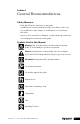
Section 1 General Recommendations Safety Measures • Read and follow the instructions in this guide. • A qualified person must install this product according to local code. • It is prohibited to make changes or modifications not specified in this guide. • Uponor is not responsible for damages or injuries that may result from not following the instructions in this guide. Symbols Used in this Manual Warning: Risk of bodily injuries. Nonobservance may harm health or cause damage to product components.
Designated Application The EP Heating Manifold distributes water through the radiant floor heating/cooling system. Typically it is installed on the wall or in a manifold cabinet (surface or concealed installation). STOP 2 Contact Uponor before modifying the EP Heating Manifold. Uponor is not liable for damage resulting from misuse. www.uponorpro.
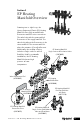
Section 2 EP Heating Manifold Overview Featuring two to eight loops, the Uponor Engineered Plastic (EP) Heating Manifold comes fully assembled with flow meters and R32 union connections. The valve body with the preassembled flow meters is the supply manifold. The valve body without the flow meters is the return manifold. The return manifold is where the actuators (if used) will mount.
Preparation Before Installation Verify product contents. Note: Manifold fittings are sold separately. Use QS-style fittings. (Refer to the Uponor Product Catalog for more information.) Tools Required • Tubing cutter • Wrench • Level • Flat screwdriver • Electric drill • Pressure testing equipment • Valve replacement tool 4 www.uponorpro.
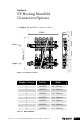
Section 3 EP Heating Manifold Connection Options See Figures 3-1 and 3-2 for connection options. 68 mm Width A 2.7" B 400mm/15.7" Return C Supply D Figure 3-1: Straight Connections E Number of Loops Part No. Width 2 A2670201 9.6" (245mm) 3 A2670301 11.6" (295mm) 4 A2670401 13.6" (345mm) 5 A2670501 15.6" (395mm) 6 A2670601 17.6" (445mm) 7 A2670701 19.5" (495mm) 8 A2670801 21.
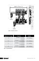
Width + 70 mm, 2.8" A 68 mm 2.7" B C Return D E Supply Figure 3-2: Angle Connections Number of Loops Part No. Width 9 A2670801 + A2670001 A2670003 23.5" (595mm) 10 A2670801 + 2 x A2670001 2 x A2670003 25.5" (645mm) 11 A2670801 + 3 x A2670001 3 x A2670003 27.5" (695mm) 12 A2670801 + 4 x A2670001 4 x A2670003 29.5" (745mm) Table 3-2: Manifold Widths 6 www.uponorpro.
Section 4 EP Heating Manifold Mounting Instructions Mounting Manifold to a Wall or Cabinet 1. Mount the bracket to the wall or in a cabinet. See Table 4-1 on page 8 for proper spacing of the bracket bars. 1 15 2. Snap the manifold into the bracket. Make sure the manifold locks into position. Listen for the click.
Number of Loops A inch (mm) B inch (mm) C inch (mm) 2 5.3 (135) 2 (50) 2.6 (65) 3 4 5 6 7 8 9 10 11 12 5.3 (135) 5.3 (135) 5.3 (135) 5.3 (135) 5.3 (135) 7.3 (185) 7.3 (185) 7.3 (185) 7.3 (185) 9.3 (235) 3.9 (100) 5.9 (150) 5.9 (150) 7.9 (200) 7.9 (200) 7.9 (200) 9.8 (250) 11.8 (300) 11.8 (300) 15.7 (400) 2.6 (65) 4.5 (115) 4.5 (115) 4.5 (115) 6.5 (165) 6.5 (165) 6.5 (165) 6.5 (165) 8.5 (215) 8.5 (215) Table 4-1: Bracket Spacing A B C Return 9.
Section 5 Installing Manifold Accessories Note: Thread tape or similar thread sealants are not necessary for assembling the manifold accessories. Installing Thermometers 1 When installing the thermometers into the manifold connections, ensure they snap in firmly until they click. Installing the Elbow Kit When mounting the Elbow Kit, follow these steps. 1. Unlock the snap lock. 2. Dismantle the connection fittings. 3. Mount the elbows.
4. Mount the connection fittings. 5. Fasten the snap lock. 4 10 5 www.uponorpro.
Mounting Additional Manifold Outlets Refer to the following instructions to properly mount one or more additional outlets on the manifold. 1. Dismantle the End Cap with Vent and Drain. 2. Mount the desired number of extra outlets and reattach the End Cap with Vent and Drain. 3. To angle some of the extra outlets in an opposite direction (e.g., up instead of down), tighten the extra outlet completely and then loosen a half turn. 2 1 B 1. 3 1. 2. 2. 1. 1. 2. 2.
Section 6 Connecting Tubing to the Manifold 1 2 1. Cut the tubing with a tubing cutter to the correct length. The tubing should reach the end of the outlet thread; ensure there is no gap. Note: Do not use a saw or anything similar to cut the tubing. Shavings may clog manifold valves. 2. Tighten the manifold fitting with the appropriate wrench. Make sure the tubing is pushed all the way into the fitting before tightening. Note: Do not overtighten or twist the tubing.
3. If you need to remove the fitting from the tubing, open the clamp ring with a screwdriver and remove the insert. 20 4. When all tubing is connected to the manifold, measure the length of each loop (subtract 30 on the the length marking W S from the supply return line line, or vice versa). Record the measurements in Section 12: Manifold Balancing Form as this information is needed for balancing. 3 m 1m 0692 23 4 12 • Date • Project • Floor No. • Manifold No. Room No.
Section 7 Filling and Purging the Manifold To ensure the manifold provides enough water for superior performance, fill and purge the system at the boiler or at the manifold. If you choose to fill and purge at the manifold, see the following instructions. 1. Connect a water hose from a faucet to the fill valve on the supply manifold cap. 2. Connect a separate drain hose to the cap on the return manifold and place the other end into a large bucket or into a drain. 3.
5. Fill the loop with water and let the water flow until the water coming out of the hose is clear (i.e., no bubbles appear). 6. Repeat Steps 1 through 5 to fill and purge each manifold loop. 6 5 max.open close close open close max.open close close min.open close max. 30 psi open Section 7 – Filling and Purging the Manifold max.
Section 8 Pressure Testing To ensure the system is installed correctly and operating properly, pressure test the system. 1. Connect pressure testing equipment to the manifold and pressurize a maximum of 87 psi for two hours. 2. When the two hours have elapsed, check that the pressure rating is the same. Note: Make sure all valves are open open 1 2 hours max. 87 psi 2 Max 87 psi After 2 hours, check for leakage. 16 www.uponorpro.
3. After the installation passes the pressure test, set the operation pressure. Note: If you choose to test with air, the max pressure should be 100 psi. Sustain the pressure for 24 hours or according to local code. 4. To ensure all valves are working accurately, open and close all valves twice.
Section 9 Adjusting Manifold Valves 4 3 1 Balance the manifold system to ensure superior performance. 2 1. Use the manifold flow meters to balance the system. 2. Make sure the system is in operation and water is flowing through the manifold. close Uponor Fußbodenheizungsberechnung Uponor floor heating calculations Uponor vloerverwarmingsberekening Calculation du chauffage par le sol Uponor Calcolo riscaldamento a pannelli radianti Uponor 3.
Section 10 Manifold Maintenance The EP Heating Manifold does not require a maintenance schedule. However, Uponor recommends checking system components regularly. Use a soft, dry cloth to clean the manifold as needed. Do not use a damp cloth or cleaning agents.
Section 11 Technical Data Technical Data Connection Dimensions R32 Max. Operating Temperature and Pressure 6 bar at 60°C 87 psi at 140°F 5 bar at 70°C 72 psi at 158°F 4 bar at 80°C 58 psi at 176°F 3 bar at 90°C 44 psi at 194°F Max. Test Pressure (24 h, ≤ 86°F) 10 bar/145 psi Max. Water Flow per Manifold 0.97 L/S or 15.4 gpm Cv Value Inlet/Outlet Valves 1.
Chemicals Do not use the chemicals outlined in Table 11-2 with the EP Heating Manifold.
Section 12 Manifold Balancing Form When all tubing is connected to the manifold, measure the length of each loop (subtract the length marking on the return line from the supply line, or vice versa). Record the measurements in the form below as this information is needed for balancing. 12 • Date • Project • Floor No. • Manifold No. Room No. 1 2 3 4 5 6 7 8 9 10 11 12 Room Designation Heating Loop No. Valve Setting/ Water Flow (gpm/ L/S) Start No. of Feet/Meters End No.
Notes EP Heating Manifold Installation Guide 23
MKT10018-AA EP_HeatMfld_InsG_H221_0411, Copyright © 2011 Uponor. Printed in the United States Uponor, Inc. 5925 148th Street West Apple Valley, MN 55124 USA Tel: 800.321.4739 Fax: 952.891.2008 Web: www.uponorpro.com Uponor Ltd. 2000 Argentia Rd., Plaza 1, Ste. 200 Mississauga, ON L5N 1W1 CANADA Tel: 888.994.7726 Fax: 800.638.9517 Web: www.uponor.