
Install Instructions

INSTRUCTION SHEET
RADIANT HEATING SYSTEMS
TRUFLOW
TM
JR.
MANIFOLD
1
4
5
2
3
4
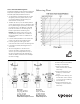
Installing Actuators
The TruFLOW manifold comes
with black plastic caps mounted
on the r
eturn manif
old f
or manual
operation of the on/off valves. To
mount either the A3020522 Uponor
Mot
orized
V
alve Actuator (MVA) or
A3010522 Uponor Thermal Actuator,
follow the directions below.
1.
R
emove the plastic cap by
loosening the lower ring with a
pair of pliers.
2.
Install the included br
ass manif
old
adapter ring A2620028 (see
below). Tighten by hand.
3. Install actuator:
a.
MVA (A3020522): Thread on
the MVA until it bottoms out
on the brass ring. The
alignment dot may not line up.
This will not affect the
operation of the end switch.
b.
Thermal Actuator (A3010522):
Thread on the green plastic
ring until it bottoms out on
the brass ring. Snap on the
actuator head until you hear
two clicks indicating that both
sides of the actuators have
seated properly.
Maximum W
orking Pr
essur
e
145 psi
Maximum Fluid
Temperature
220°F
Manifold Flow Capacity 14 gpm
Loop Flow Capacity
C
v
= 1.9 gpm
Loop Connection R20
TruFLOW
TM
Jr
.
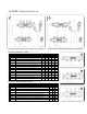
Assemblies
TruFLOW
TM
Jr. Manifold System
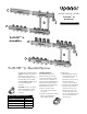
TruFLOW Jr. Manifold Specifications
The TruFLOW Jr. manifold assemblies
(
Figures 1 and 2 above) feature an
R32 union to connect either an
Uponor Manifold Adapter or any of
the TruFLOW Jr. add-on modular
manifolds (
Figures 3, 4 and 5 above).
Use a wrench to tighten the
connection.
Important: Be sure to use the flat
gasket supplied with the manifold.
Do not over-tighten the union
connection.