UP mini 2 User Manual V 0.1 Download the full user manual at www.up3d.
Index Chapter 1 Product Description Chapter 2 Prepare for Your First 3D Print Chapter 3 Product Activation Chapter 4 Machine Settings Chapter 5 Print Settings Chapter 6 Calibration and Other Options Chapter 7 Techniques and Troubleshooting
Safety Precautions 1\ The UP mini 2 3D printer requires the power adapter provided by the original manufacturer, otherwise the machine could be damaged or even cause are hazard. Please also keep the power adapter away from water and out of high temperature environments. 2\ During printing, the nozzle of the printer will reach 260°C and the print platform could reach over 70°C.
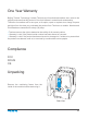
One Year Warranty Beijing Tiertime Technology Limited (Tiertime) and its authorized resellers war- rants to the original purchaser that this product is free from defects in material and workmanship. Tiertime or its resellers will for one year, at its option, repair or replace at no charge for parts and labor from the date you purchased the product from Tiertime or a reseller. Nozzles and Print Boards are warranted for ninety (90) days.
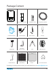
Package Content UP mini 2 Protective Gloves Spool and Toll Holder Power Adapter Calibration Card Power Cable USB Cable Hex Keys 2.0mm, 2.5mm Plier Nozzle Wrench Perforated Print Board (Perf Board) UP Flex Print Board 50g Tester PackX3 Scraper ABS Filament Print Head Nozzle If anything is missing, please contact your local distributor or at support@pp3dp.
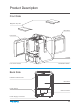
Product Description Front Side Magnetic Top Lids Back Door Front Door Handle LCD Touch Screen Initialization Button Back Side Filament Insertion Hole Back Door Power Switch USB Connector Power Supply Connector 04
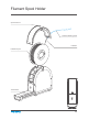
Filament Spool Holder Spool Hold Lid Filament Guiding Tube Filament Filament Spool Tool Drawer 05
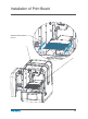
Installation of Print Board Slide print board into the platform 06
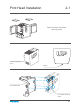
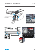
Print Head Installation 2-1 Open front door, back door and top covers Cooling Adjustment knob Nozzle Print Head Mount Print Head Mounting Plate 07
Print Head Installation 2-2 Slide the print head into the slots. Plug in the print head cable.
Download and Install UP Studio Two ways to obtain UP Studio 1. From the Micro SD card included in the package (using the mciroSD reader). 2. Download the latest version from www.up3d.com. Double click the installationle, following simple instructions, the installation will be nished swiftly. Minimum hardware requirements Intel Pentium 4 or better CPU 4GB RAM Display card support OpenGL 2.
Software Interface Printer Status Other Options Home Load File Print Initialize Calibrate Maintenance Build Platform Model Adjustment Wheel Mirror Move Rotate Scale To Menu 2 Auto Place Undo View Angles Menu 1 Back to Menu 1 Save Merge Fix Delete Undo Reset Menu 2 10
Initialization of Printer Initialization is required for every time the machine is switched on. During initiali- zation, the print head and print platform move slowly and hit the endstops of the XYZ axes. This is essential as the printer needs to nd the endpoint of each axis. Many software options will light up and become available for use only after initiali zation. Initialization button There are three ways to initialize your printer: 1. Hold the initialization button on the printer. 2.
Printer Activation Activation will lift the restriction of the number of prints, and provide value-added services for the users. 1\ Click the“Account”button at the main menu to Sign Up. 2\ If already registered, skip to step 5. Account Fill in the form. 3\ Go to your registered mail box, and 4\ Connect UP mini 2 to your computer. 5\ Go to 6\ You will see a list of connected activate your account through the activation email. Account section and sign in. printers.
Touch Screen Control Change printing Material Print a stored project Printer Info, reset to factory and choose language Nozzle Height Detection Nozzle Temperature Platform Tem-perature Machine settings including Wi-Fi Initialize the printer WIFI Status Remaining material Private setting status Printer readiness status 13
Prepare for Printing - Update Nozzle Height The printer was calibrated before leaving the factory, but users are recommend to update the nozzle height value using the automatic nozzle height detection function on the touch screen before the first print. Press “Calibrate” button to enter Nozzle Height setup page. Press the “Auto” button to start the automatic process. 128 Auto During nozzle height detection, the print head nozzle will touch the nozzle detector to make measurement.
Prepare for Printing - Load Filament 2-1 install the lament and guiding tube shown in blue. Front To printer Push the guiding tube into the rubber ring as shown above.
Prepare for Printing - Load Filament 2-2 Back Side Filament Guiding Tube insert into the filament entrance.
Prepare for Printing - Load Filament 1\ Insert the filament from the spool into guiding tube, arrange the guiding tube as shown in previous page. Press the Material button on the touch screen. 1\ 2\ 3\ 2\ Choose the printing material as ABS by press the Wheel button to switch between different materials input the filament weight by using the +/- buttons. 3\ Click "Extrude." The print head will start to heat up, within 3 minutes.
Loading a 3D Model Load Model Button 18
Print a Model Make sure printer is connected to computer throug USB or WIFI ( go to page 25 for details about WIFI setting)and loaded a model. Click print button to open the print interface Set Layer Thickness Select Infill Type Select Print Quality/Speed Advanced Options Shell: No infill, normal wall. Surface: No top and bottom layers, no infill, single perimeter.
Printing Progress Print job progress Pause print job After pressing the pause button, the nozzle will be paused but temperature is maintained at printing temper- ature. During pausing, the following control buttons will appear to allow users to resume, stop or change filament. Please note the stopping is irreversible, the current print job can only be restarted from begining.
Change Filament During Printing 1\ During printing process the “Pause” button, the printing job will be paused. 2\ When print head stopped moving and platfrom lowered. Press the “Retract” button to remove filament. Press the “Extrude button” to load the new filament Press the “resume” button to resume printing. After filament was removed, insert new filament to the print head as described in page 16.
Reprint or Printing Stored Print Jobs Info of the stored file print job Start Printing Test001 Test002 Stored file name Change Page Black Out Recovery If electricity was cut off during printing, the print job can be contuinued after resuming power supply. Do not remove the print job from the platform after the black out. When the machine was turn on again, initialize the printer. The printer will ask whether user would like to recover interrupted print job.
Machine Settings - WIFI Connection or Connecting to the UP mini 2 through WIFI requires a Wireless Local Area Network (WLAN). Computer and printers must connect to the same WIFI network (same SSID) before able to communicate. In order to acheive stable WIFI connection, users are recommended to connect under a capacious WIFI environment. A crowded network or an area with a large number different networks are known to cause interruption during data trasnfer.
WIFI Setup through Touch Screen. SSID Input Input WIFI Password Select WIFI IP address Private setting, which add password for WIFI connection.
Setup Private WIFI Access If user switch on the private function in WIFI setting, a password field will appear to allow passowrd setup. This is password that will be required for WIFI connection to the printer to prevent unathorized usage through WIFI. Please note this is a weak protection that anyone who can access to the printer through USB or touch screen could changet the private password.
WIFI Setup (UP Studio) 1\ 3-1 Connect UP mini to computer through USB. 2\ At top right corner click the setting button and then click WIFI tab.
WIFI Setup (UP Studio) 3-2 3\ Click network to choose an available network ( user can also use touch screen panel to setup WIFI connection). Choose your network from the drop down list.
WIFI Setup (UP Studio) 4\ 3-3 Input the password for the WIFI network. 5\ If “Private” is set to ON, a private password could be optionally added to limit printer WIFI access to trusted users. Please note that the password is a weak protection that can be accessed and changed by anyone who can connect the machine through USB. 6\ Printer Tab Disconnect USB and choose available printers on the network to operate through WIFI.
Set Materials (Touch Screen) Decrease Material Weight adjustment Increase current material weight Save current setting Stop extru-sion and heating Back withdraw material Change Ma- terial extrude material Set Materials (UP Studio) Extrude Filament Withdraw Filament Stop All Actions Select Material Input Material weight 29
Set Nozzle Height (UP Studio) For setting nozzle height with touch screen please refer to page 16. 120.90 Open the Calibration panel At the Nozzle Height section, click “Auto” will initiate the automatic nozzle height detection process. Clicking +/- button will move the platform up and down, or user could input a specific value at the text field and click “To” button the move the platform to a specific height. Click save will replace nozzle height value with current platform height.
Machine Configuration WIFI switch, if swithed off the WIFI setting button will not appear. internal lighting switch WIFI setting button Peheat switch, when turned on, for every print job, the printer will first preheat 15min before proceed to printing.
Language and Factory Reset Model: current machine model S.N.: machine serial number Firmware Ver: shows current firmware version Print Time: total print time count Print Weight: total print weight count Actived Date: the date of printer activation MAC: mac address of printer Reset: revert to factory setting. This will change some machine setting to default; remove total printed time and weight data. Language: choose language.
Error Prompts Suggested solution, in this case: Contact support Error Message Error code Other possible error prompt: Unplug printer and restart reinitialize the printer 33
Rotating Models (UP Studio) Choose the model and Click rotate button. Choose rotation axis User could input a specific value or choose a preset value for rotation. Alternatively, user could use the rotation guide to rotate model in real time by hold and drag with mouse.
Scaling Models (UP Studio) Choose the model and Click rotate button. By default the scaling is in all axes. User could also choose a specific axis for scaling. User could input a specific scaling factor or choose a preset value Click MM or INCH to convert models to sizes of corresponding units. Alternatively, user could use the scaling guide on the model. User could scale in a specific axis or scale in all directions by hold and drag with mouse.
Move Model (UP Studio) Choose the model and click the Move button. Choose the the direction of movement User could input a specific value or choose a preset value for distance of movement. Alternatively, user could use the translational guide on the model to move on the X-Y plane or a single direction by hold and drag with mouse.
Make Copies Choose the model by clicking it (hight lighted),the right-click to bring up the menu and select copy number. Repair A Model 1\ If the model contains defective surfaces, the software will highlight the surfaces in red.Click the "more" button to reach second level menu 2\ Click the x button the repair the model.The red defective surfaces will resume a normal color when repaired.
Merge and Save Models 1\ Ctrl/CMD click all the models on the build plate 2\ The Merge button on the second level of the adjustment wheel will become available, click to merge the models. 3\ Click the save button to save the merged models to comptuer.
Print Preference 2-1 Surface: the number layers at the sealing the top and the bottom of the printed object. Angle: This determine at which angle the Surface layers start to be printed. Dense: Choose the number of dense layers between support and supported surfaces. Angle: Determine the angle which support and dense layer to generated. Area: Determine the minimal area of surface that will be supported, area less than this vaule will not be supported.
Print Preference 2-2 No Raft: print without raft. No Support: print without support Stable Support: Support structure will be stronger but less easy to be removed. Unsolide Model: The software will autofix nonsolid models Thin Wall: The Software will detect wall thickness that is too thin to print and expand the feature to a printable size. Keep Heating: The platform will be heated after print job is completed.
Printing Parameters Surface Infill Surface Support Dense (support) Raft Print Platform Suppot Range: < 30o Support Range: < 90o Dense: Solid support structure ensures that the surface being supported retains its shape and surface finish. Infill: The inner structure of the printed object. The density of the infill can be adjusted. Raft: The thick structure that assists with the adhesion of the object to the plat- form. Surface: The top and bottom layers of the printed object.
Manual Calibration The 9 buttons represent platform calibration point. The dropdown menu beside the button is for setting the leveling compensation values. After chekcing the leveling check box and clicking these buttons, the nozzle will move to the corresponding positions and move up base on the compensa- tion value. Moves the platform up/down: click the +/- buttons to move the platform up and down. 120.
1\ Initialize the printer 2\ Put a Calibration Card on the plat- form. 3\ Move print head to the middle of the platform by click 5. 4\ Raise the platform until it is just touching the nozzle. Move the Calibration Card between the nozzle and the platform to see if there is any resistance.
Platform too high, nozzle is pinning Calibration Card onto platform, Lower the platfrom slightly. Just right, can feel some resistance when moving the paper. Platform too low, no resistance at all when moving Calibration Card, raise the platform slightly. 5\ When the ideal platform height is obtained, record the platform height value. Repeat steps 1–6 for all of the other eight positions and note their platform height values.
Printer Info Printer info will be displayed by clicking the small button on the top left hand corner of the connected printer icon. Information including printer type, serial number and firmware version will be displayed. User could also set a custom name for the printer at the name field.
Software Version and Update Check Auto Update to allow the software to inform user the latest version.
Convert Picture Into 3D Model 2-1 Click add picture button and select a picture. The Base height determine the thickness of The convert negative button will reverse a flat layer that will hold the picture. the pixel intensity so that user could Model Height determine the contrast of the finally print. choose the picture to be protruding from or sunken into the base.
Convert Picture Into 3D Model 2-2 Update 3D model button. This button will convert the modi- fied picture on the left to a 3D rendering on the right. OK button send the 3D rendering to the 3D printing interface for printing.
Printing Techniques 1. Ensure accurate nozzle height. If the nozzle height value is too low, it will cause warping; if it is too high, it will crash the nozzle into the platform,causing damage and clogging. You can manually fine-tune the nozzle height value in the"Calibation"panels.You can try to adjust the nozzle height value plus or minus 0.1–0.2mm from the base on previous results. 2. Calibrate the printing platform well. An unleveled platform usually causes warping.
Printer Maintenance - Air Filter Replacement Change air filter for air filatraton unit. It is recommmended to change the filter for every 300 hours of usage or 6 months. Air Filtration Unit Front View Turn anti-clockwise to open the cap.
Print Head Maintenance The printhead cover could be removed after unscrew 2 bolts. Heat up the nozzle to printing temperature by using the extrude function in maintenace interface. Nozzle could be removed by using the nozzle wrench provided. User does not need to remove printhead cover in order to remove nozzle.
Printer Maintenance - remove motherboard cover Remove the 3 screws and FFC cable clip on the mainboard cover.
Beijing Tiertime Technology Co., Ltd youtube.com/c/UP3DPrinters facebook.com/up3dp/ instagram.com/up3dprinter/ twitter.com/UP3DP Support: support@pp3dp.com Web: www.tiertime.com www.up3d.