Chapter 5 Troubleshooting Guidelines 1.1 System features 1.1.1 General features a. Support cost efficient CPU, - Celeron-128K Socket 370 Type FCPGA 500~700 MHz - Pentium III Socket 370 Type FCPGA 500~1.0GHz b. Superior portability with all in one design c. Support high quality audio include 2 internal high power speaker d. Fully Support ACPI 1.0, meet PC98/PC99 requirement e. Built-in 56K modem for Data/Fax/Voice modem or Internet (optional) f.
Chapter 5 Troubleshooting Guidelines g. Support high capacity memory up to 256 MB h. Support one most flexibility of 32-bit Cardbus slot and PCMCIA card 1.1.2 Hardware specification A. CPU: Celeron-128K 500MHz to 700MHz • System bus frequency at 66 MHz • Dynamic execution micro-architecture • MMX technology capability • Optimized for 32 bits AP and OS • Power Management capability • Integrated 32KB instruction and data L1 cache • Integrated 128 KB instruction and data L2 cache Pentium III 500MHz and 1.
Chapter 5 Troubleshooting Guidelines C. PCMCIA Controller O2 Micro OZ6812 • ACPI-PCI bus power management interface specification Rev.1.0 compliant • Compliant with PCI specification V2.1S, 1995 PC Card Standard and JEIDA 4.1 • Supports PCMCIA ATA specification • Supports 5V/3.3V PC Cards and 3.
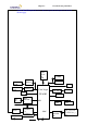
Chapter 5 Troubleshooting Guidelines System Block Diagram shows how these components are integrated as shown in the next page. CPU Sock et 370 DS90C F363A TFT LCD Host Bus DSTN LCD CS9211 CR T RJ45 SLOT 1 DIMM 2 DIMM 1 Core Logic SIS 630S PHY RTL820 1 Alc 200 US B LM483 5 SMBu s PCI HD D PCMCI A OZ6812 Moden 340S8 LPC Rev : A Conn. RT CPU POWE R Page CDROM Cpu_core,+1.8 V,+2.
Chapter 5 Troubleshooting Guidelines 1.2.2 LCD Display 14.1” TFT 13.3” TFT 12.1” TFT 1.2.3 Power Plans Power Source Descriptions +5V : 5V power source +3V : 3.3V power source +12V : 12V power source CPU_Core : CPU Core power source. For Celeron, the voltage is 2.0V For Pentium III, it is 1.7V +2.5V : 2.5V power source +1.8V : 1.8V power source for SIS630 & CPU AGTL + termination power source KBVCCA : KBC AD/DA 3.
Chapter 5 Troubleshooting Guidelines +3V_TX_TR : LAN 3.3V analog power source LCDVCC : LCD display 3.3V power source VIN : Inverter 8~20V power source ADAP+ : 20V Power supply from AC adapter AMPVDD : 5V analog power for audio 1.2.4 Power Source Status FULL-ON SLEEP STD SOFT-OFF 5V 3.3V 12V ON ON OFF OFF ON ON OFF OFF ON ON OFF OFF CPU _core ON ON OFF OFF VCC_ CMOS ON ON OFF OFF 2.5V 1.5V 1.8V ON ON OFF OFF ON ON OFF OFF ON ON OFF OFF 1.2.
Chapter 5 • • Troubleshooting Guidelines Battery power : 47.36 watts (total) Battery protection : over charge protect, over discharge protect, over temperature protect, short protect, over current protect B. Ni-MH battery packs • Battery type : Ni MH • Battery cells : 10 cells • Battery specs : 12V, 3800 mAh • Battery power : 45.6 watts (total) • Battery protection : over charge protect, over discharge protect, over temperature protect, short protect, over current protect 1.2.
Chapter 5 08 09 09 10 10 10 10 11 11 11 11 12 13 14 14 15 15 Troubleshooting Guidelines System CMOS/ Real Time Clock (RTC) ACPI IRQ Holder for PCI IRQ Steering SiS 900 PCI Fast Ethernet Adapter ACPI IRQ Holder for PCI IRQ Steering HAMR 5600 Voice Modem O2Micro OZ6812 CardBus Controller SIS 7018 Audio Driver ACPI IRQ Holder for PCI IRQ Steering SIS 7001 PCI to USB Open Host Controller SIS 7001 PCI to USB Open Host Controller SCI IRQ used by ACPI bus Microsoft PS/2 Port Mouse Numeric data processor SIS 551
Chapter 5 Troubleshooting Guidelines 1.2.13 Hot Key: Key combination Fn + F1 (SMI) Fn + F4 (SMI) Fn + F5 (SMI) Fn + F6 (SMI) Fn + F7 (SMI) Fn + F8 (SMI) Fn + F9 (SMI) Fn + F10 (SMI) Function Standby Mode Toggle LCD / CRT display Volume increase Volume decrease Brightness up Brightness down Contrast up (for DSTN LCD) Contrast down(for DSTN LCD) UNIWILL COMPUTER CORP. No.24, Pei Yuan Rd., Chung Li Industrial Park Chung Li City, Taiwan, R.O.C. TEL: 886-3-461-6000 FAX: 886-3-461-6317 URL: http:// www.
Chapter 5 Troubleshooting Guidelines 2.1 Connector Definitions 2.1.
Chapter 5 Troubleshooting Guidelines CN27 1 3 5 7 9 11 13 15 17 19 21 23 25 27 29 MONO_OUT GND AUXR AUXL CDGND CD_R CD_L GND 3.3V GND 3.3V SDATA_O RESET# GND MCLK 2 4 6 8 10 12 14 16 18 20 22 24 26 28 30 AUDIO_PD MONO_PHONE R_D GND VCC R_D R_D P_DN VCC GND SYNC SDATA_INB SDATA_INA GND BCLK MDC CON. 2.1.3 SIS 630S Clock DIP Switch (SW3) Frequency Selection +3V 1 BSEL0# 1 BSEL1# R68 10K R67 10K RP3 8P4RX4.
Chapter 5 Troubleshooting Guidelines CN35 1 2 F1 3216FF/2A-1206 MIC CONN CN2 11 L59 INT_MIC 1 2 3 4 5 6 7 8 BLM11P600S BLTADJ DISPON INVERTER 1 17 L58 2 + C58 BLM11P600S 1u/25V 2.1.5 USB Connector (CN20) +5V S3 L62 150u/6V3_D3 1 BLM21300S_0805 POLY SW_1812 C230 + C97 0.1u 1u USBGND 2 C267 USBGNDUSBGND CN20 5 5 USBP0USBP0+ L17 L57 1 2 3 4 BLM11P600S BLM11P600S C239 C36 47p 47p 5 6 USB CONN USBGND USBGND 2.1.
Chapter 5 Troubleshooting Guidelines MODEM L82 21-v60615-00 60uH_SBT_0260_DIP2KV CN22 3 CN19 1 2 1 2 4 L83 MODEM-PHONE MODEM CONN 60uH_SBT_0260_DIP C246 C255 2KV USBGND 1000p/2KV_1808 21-v60615-00 1000p/2KV_1808 USBGND 2.1.8 LAN - RJ45 Connector (CN16) CN16 8 7 6 5 4 3 2 1 NC4 NC3 RONC2 NC1 RO+ TDTD+ GND GND 9 10 RJ45 2.1.
Chapter 5 Troubleshooting Guidelines L35 BLM11P600S CN12 5 4 3 2 1 EXTSPKR EXTSPKHP EXTSPKL BLM11P600S L34 C242 0.1u C234 0.1u C C L31 SPKR JACK BLM11P600S C548 0.1u C AUDGND AUDGND AUDGND 2.1.10 R/L Speaker Connector (CN3) CN3 L2 L12 L13 L11 BLM11P600S BLM11P600S BLM11P600S BLM11P600S RR+ L+ L- 4 3 2 1 R/L SPKR CONN C32 C31 C30 C29 C C C C AUDGND 2.1.
Chapter 5 Troubleshooting Guidelines CN28 51 17 52 18 19 54 20 53 50 49 13 14 59 60 15 16 48 33 58 32 40 47 43 57 36 67 62 63 (D10) CAD31 (D9) CAD30 (D1) CAD29 (D8) CAD28 (D0) CAD27 (A0) CAD26 (A1) CAD25 (A2) CAD24 (A3) CAD23 (A4) CAD22 (A5) CAD21 (A6) CAD20 (A25) CAD19 (A7) CAD18 (A24) CAD17 (A17) CAD16 (IOWR*) CAD15 (A9) CAD14 (IORD*) CAD13 (A11) CAD12 (OE*) CAD11 (CE2*) CAD10 (A10) CAD9 (D15) CAD8 (D7) CAD7 (D13) CAD6 (D6) CAD5 (D12) CAD4 (D5) CAD3 (D11) CAD2 (D4) CAD1 (D3) CAD0 VPP VPP CCLK (A16) CF
Chapter 5 Troubleshooting Guidelines V_CDROM V_CDROM CN23 SIDECDL 11 CDGND R462 1 3 5 7 9 11 13 15 17 19 21 23 25 27 29 31 33 35 37 39 41 43 45 47 49 1K R463 R533 100K R AUDGND CDRST# SIDED7 SIDED6 SIDED5 SIDED4 SIDED3 SIDED2 SIDED1 SIDED0 SIDEIOW# SIORDY 4 IRQ15 SIDEA1 SIDEA0 SIDECS1# 16 CD-ROMLED# R49 10K SIDECDR 2 4 6 8 10 12 14 16 18 20 22 24 26 28 30 32 34 36 38 40 42 44 46 48 50 SIDED8 SIDED9 SIDED10 SIDED11 SIDED12 SIDED13 SIDED14 SIDED15 SIDEDREQ SIDEIOR# SIDEDACK# SIDEA2 SIDECS3
Chapter 5 Troubleshooting Guidelines CN17 26 LPTSLCT LPTPE LPTBUSY LPTACK# LPTD7 LPTD6 LPTD5 LPTD4 LPTD3 LPTSLCTIN# LPTD2 LPTINIT# LPTD1 LPTERR# LPTD0 LPTAFD# LPTSTB# 13 25 12 24 11 23 10 22 9 21 8 20 7 19 6 18 5 17 4 16 3 15 2 14 1 27 PARALLEL CONN 2.1.17 Serial Connector (CN18) CN18 10 5 9 4 8 3 7 2 6 1 COMRI1 COMDTR1# COMCTS1# COMTXD1 COMRTS1# COMRXD1 COMDSR1# COMDCD1# 11 SERIAL CONN 2.1.
Chapter 5 Troubleshooting Guidelines S1 L8 +5V POLY SW_1812 BLM11P600S BLM11A221S BLM11A221S KBCLK PS2CLK L4 L7 BLM11A221S BLM11A221S C25 CN14 1 2 3 4 5 6 C22 C23 C24 1 KBDATA PS2DATA L5 L6 C231 270p 270p 270p 270p 2 + PS2 CONN 1u USBGNDUSBGNDUSBGNDUSBGND USBGND USBGND 2.1.
Chapter 5 Troubleshooting Guidelines Q37 SI2301DS-SOT23 D 2.1.22 Fan 1 (CN24) and Fan2 (CN25) Connector +5V S G CN25 +5V 1 1 2 FANON# C385 2 Q36A SI9953 FAN2 CONN 7 8 0.1u CN24 2 1 C386 FAN1 CONN 0.1u L89 BLM11P600S 2.2 Mechanical Buttons and Switch Definition 2.2.1 Power on/off button 1.
340S8 Rev : A PC87570-ICC/ VPC U19 PC87393 VJG U14 Page T/P conn. CN11 CN8 K/B conn. BIOS U17 CN31 O2 Micro U22 CN2 LCD connectors WWW switch SW 1 SiS 630S Memory socket #2 CN5 -Memory socket # 1 LEDs CN3 SPEAKER conn. FDD conn. CN10 Power SW SW6 LID switch conn. Chapter 5 Troubleshooting Guidelines 2.3.1 Top Side 2.3.
340S8 IR PS/2 conn CN14 U 24 CPU SOCKET USB conn Modem DC-IN conn. ext. MIC spkr CN12 CN13 HDD connector CN15 ext. CRT conn CN 24 CPU FAN conn. CMOS Batt. C N 2 6 CN17 Printer conn. Rev : A CN 29 Battery connector MODEM connector CN27 C N CD-ROM 23 connector COM 1 CN18 C N 2 8 PCMCIA SLOT LAN conn.
Chapter 5 Troubleshooting Guidelines UNIWILL COMPUTER CORP. No. 24, Pei Yuan Rd., Chung Li Industrial Park Chung Li City, Taiwan, R.O.C. TEL: 886-3-461-6000 FAX: 886-3-461-6317 URL: http://www.uniwill.com.
Chapter 5 Troubleshooting Guidelines 3.1 Major Component List Reference Component Part Number U1 U2 U3 U4 U6 U8 U10 U11 U12 U13 U14 U18 U19 IC ALC-200 LQFP IC RTL8201 LQFP48P PHY IC GD75232 SOP20P RS-232 IC LM4835 TSSOP-28 IC ADM1021 16 PIN QSOP IC DS90C363A TSSOP48P LVDS SIS 630S BGA 762 PIN MULTI-FUNCTION IC SN74LVC14 14 PIN (T1) IC 74LVC08 QUAD 2 – INPUT IC 74LVC 32 0.
Chapter 5 Troubleshooting Guidelines Y33 C37 AL31 AL29 AH28 W37 AK20 AN19 AN25 AH4 X4 AN17 AN29 AK28 AH22 AH26 THERMDP THERMDN THERMTRIP# BCLK LOCK# DEFER# TRDY# RESERVED/RESET# RESET#/RESET2# BPRI# BREQ0# RS#[2] RS#[1] RS#[0] ADS# HITM# HIT# DRDY# DBSY# BNR# REQ#[4] REQ#[3] REQ#[2] REQ#[1] REQ#[0] RESERVED/A#[35] RESERVED/A#[34] RESERVED/A#[33] RESERVED/A#[32] A#[31] A#[30] A#[29] A#[28] A#[27] A#[26] A#[25] A#[24] A#[23] A#[22] A#[21] A#[20] A#[19] A#[18] A#[17] A#[16] A#[15] A#[14] A#[13] A#[12] A#[11
Chapter 5 Troubleshooting Guidelines U24B AA37 AA5 AB2 AB34 AD32 AE5 AF2 AF34 AH24 AH32 AH36 AJ13 AJ17 AJ21 AJ25 AJ29 AJ5 AJ9 AK2 AK34 AM12 AM16 AM20 AM24 AM28 AM32 AM4 AM8 B10 B14 B18 B22 B26 B30 B34 B6 C3 D20 D24 D28 D32 D36 D6 E13 E17 E5 E9 F14 F2 F22 F26 F30 F34 F4 H32 H36 J5 K2 K32 K34 M32 N5 P2 P34 R32 R36 S5 T2 T34 V32 V36 W5 X34 Y35 Z32 VCC_CORE VCC_CORE VCC_CORE VCC_CORE VCC_CORE VCC_CORE VCC_CORE VCC_CORE VCC_CORE VCC_CORE VCC_CORE VCC_CORE VCC_CORE VCC_CORE VCC_CORE VCC_CORE VCC_CORE VCC_CORE
Chapter 5 Troubleshooting Guidelines U5 1 2 3 4 5 6 7 8 NC NC VCC STBY# DXP SMBCLK DXN NC NC SMBDATA ADD1 ALERT# GND ADD0 GND NC 16 15 14 13 12 11 10 9 ADM1021 T25 W28 W27 Y29 Y27 Y26 AA28 AA26 AB28 AB26 AC29 AC27 AC25 AD28 AD27 Y25 AG22 AJ22 AF21 AH21 AF20 AH20 AJ20 AG19 AJ19 AF18 AH18 AF17 AG17 AJ17 AF16 AH16 T24 W29 U25 W26 Y28 V25 AA29 AA27 AB29 AB27 V24 AC28 AC26 AD29 W25 AD26 AF22 AH22 AE23 AG21 AJ21 AG20 AE22 AF19 AH19 AE18 AG18 AJ18 AD20 AH17 AE21 AG16 SIS-630S HOST and DRAM Interface (U10A)
N1 P4 P5 P3 H3 H2 H1 J2 B11 M6 J3 L4 IDEAVDD AD31 AD30 AD29 AD28 AD27 AD26 AD25 AD24 AD23 AD22 AD21 AD20 AD19 AD18 AD17 AD16 AD15 AD14 AD13 AD12 AD11 AD10 AD9 AD8 AD7 AD6 AD5 AD4 AD3 AD2 AD1 AD0 IDECSA#[1] IDECSA#[0] INTA# INTB# INTC# INTD# IDE AF10 AJ9 AG13 IIOR#[B] AF13 IIOW#[B] AJ13 IDACK#[B] AG14 IDSAB[2] AF14 IDSAB[1] AD18 IDSAB[0] AJ14 IDECSB#[1] AH14 IDECSB#[0] SIS-630S SIS-630S Power (U10C) 340S8 AH8 AF8 AJ8 AH13 ICHRDYB AD17 IDREQ[B] AF15 IIRQB AG15 CBLIDB SERR# PAR DEVSEL# PLOCK# PCICL
H9 Y22 T22 N22 M8 L8 J18 H18 H12 H11 AB20 AB18 AB13 AB11 AB10 PVDD PVDD PVDD PVDD PVDD PVDD PVDD PVDD PVDD PVDD PVDD PVDD PVDD PVDD VSSD VSSD VSSD VSSD VSSD VSSD VSSD VSSD VSSD VSSD VSSD VSSD VSSD VSSD VSSD VSSD VSSD VSSD VSSD SIS-630S POWER IVDD IVDD IVDD IVDD IVDD IVDD IVDD IVDD IVDD IVDD IVDD IVDD IVDD IVDD IVDD IVDD IVDD IVDD IVDD IVDD IVDD IVDD VSSQ VSSQ VSSQ VSSQ VSSQ VSSQ VSSQ VSSQ VSSQ VSSQ VSSQ VSSQ VSSQ VSSQ AUX3.3V AUX1.
R4 R5 V6 P2 P1 U6 VBCLK/ST2 VBVSYNC/ST1 VBHSYNC/ST0 VBHCLK/RBF# VBCTL0/WBF# VBCTL1/PIPE# VBCAD/AREQ# VGCLK/AGNT# B7/AFRAME# B6/AIRDY# ATRDY# ADEVSEL# ASERR# APAR ASTOP# R6 T6 AB2 Y6 AB3 AB4 AB6 AA5 AB5 U3 AA3 AC1 AG2 R0/AC/BE3# B4/AC/BE2# AC/BE1# AC/BE0# SBA7 SBA6/G4 SBA5/G5 SBA4/G6 SBA3/G7 SBA2/DDC2CLK SBA1/DDC2DAT SBA0/BBLANK# AAD0 AAD1 AAD2 AAD3 AAD4 AAD5 AAD6 AAD7 AAD8 AAD9 AAD10 AAD11 AAD12 AAD13 AAD14 AAD15 AAD16/B5 AAD17/B2 AAD18/B3 AAD19/B0 AAD20/B1 AAD21/R1 AAD22/R2 AAD23/R3 AAD24/R4 AAD25/
Chapter 5 Troubleshooting Guidelines U18 1 25 35 43 22 15 7 VDDREF CPU_C0 CPU_C1 CPUCS_C2 VDDSDR VDDSDR VDDSDR VDD48 VDDAGP FS1/PCICLK_F FS2/PCICLK1 PCICLK2 PCICLK3 VDDPCI PCICLK4 4 19 18 29 32 39 14 PCICLK5 GNDREF GND48 GNDAGP GNDSDR GNDSDR GNDSDR FS3/REF0 AGPSEL/REF1 CPUSTP#/SDRAM11 PCISTP#/SDRAM10 SDRSTOP#/SDRAM9 PD#/SDRAM8 SDRAM7 SDRAM6 SDRAM5 SDRAM4 SDRAM3 SDRAM2 SDRAM1 SDRAM0 SDRAM12 VDDCPU GNDCPU SCLK SDATA 13 3 2 5 21 20 27 28 30 31 33 34 36 37 38 40 41 42 26 17 16 X2 AGPCLK1 AGP
22 21 20 19 18 16 1 23 24 46 47 32 36 48 Troubleshooting Guidelines MII/SNIB LDPS ANE DUPLEX SPEED TPRX+ TPRX- RXDV RXD0 RXD1 RXD2 RXD3 RXC COL CRS RXER TPTXTPTX+ RTT3 REPT ISOLATE RTSET X1 LED0/PHYA0 LED1/PHYA1 LED2/PHYA2 LED3/PHYA3 LED4/PHYA4 X2 RESETB U25 44 41 37 38 39 1 2 4 6 8 19 17 15 13 11 31 30 33 34 27 40 43 28 OE1# I-0 I-1 I-2 I-3 OE2# I-4 I-5 I-6 I-7 VCC O-0 O-1 O-2 O-3 GND O-4 O-5 O-6 O-7 20 18 16 14 12 10 3 5 7 9 74LVC244 9 10 12 13 15 DGND DGND AGND AGND AGND 42 TXEN TXC TX
Troubleshooting Guidelines AVDD AVDD RESET# BITCLK SYNC SDOUT SDIN 35 36 37 27 28 VREF VREFOUT 29 30 AFILT1 AFILT2 31 32 33 34 43 44 45 46 47 48 39 40 41 AFILT3/CAP1 CAP2 M-VREF/CAP3 M-AFILT/CAP4 HXAN/CAP5 HXAP/CAP6 TXAN/CAP7 TXAP/CAP8 RXAN/CAP9 RXAP/CAP10 HPOUT-L/CAP11 HPOUT-C/CAP12 HPOUT-R/CAP13 4 7 AGND AGND CD-GND PC-BEEP PHONE AUX-L AUX-R VIDEO-L VIDEO-R CD-L CD-R MIC1 MIC2 LINE-L LINE-R GND GND 12 13 14 15 16 17 18 20 21 22 23 24 U1 LINEOUT-L LINEOUT-R MONO-OUT AVANCE_ALC200_SQFP-48 2
12 27 37 48 13 21 32 28 29 31 33 36 34 35 1 2 20 59 70 62 IDSEL PCI_CLK DEVSEL# FRAME# IRDY# TRDY# STOP# PAR PERR# SERR# REQ# GNT# RST# RI_OUT#/PME# SUSPEND# SPKR_OUT# MF6 MF5 MF4 MF3 MF2 MF1 MF0 73 74 71 72 VCCD0#/VCC5#/SDAT VCCD1#/VCC3#/SCLK VPPD0/VPP_PGM/SLAT VPPD1/VPP_VCC 63 Troubleshooting Guidelines AUX_VCC 14 66 86 102 122 138 CORE_VCC CORE_VCC CORE_VCC CORE_VCC CORE_VCC CORE_VCC C/BE3# C/BE2# C/BE1# C/BE0# 6 22 42 58 78 94 114 130 69 68 67 65 64 61 60 AD31 AD30 AD29 AD28 AD27 AD26 AD25 AD2
Chapter 5 Troubleshooting Guidelines U21 9 11 13 6 1 2 3 4 V3IN V5IN V5IN VCCOUT VCCOUT VCCOUT VPPOUT VPPIN FLAG# V5_EN V3_EN EN0 EN1 GND 8 10 12 7 5 14 MIC2562A Super I/O Controller (U14) 15 16 17 18 8 9 12 11 7 6 10 19 20 21 22 23 24 25 26 27 28 29 30 31 32 33 34 LAD0 LAD1 LAD2 LAD3 LCLK LRESET# LFRAME# LDRQ# LPCPD# CLKRUN#/GPIO36 SERIRQ SMI#/GPIO35 PC87393 PD0/INDEX# PD1/TRK0# PD2/WP# PD3/RDATA# PD4/DSKCHG# PD5/MSEN0 PD6/DRATE0 PD7/MSEN1 PNF/XRDY SLCT/WGATE# PE/WDATA# BUSY_WAIT#/MTR1# ACK#
Chapter 5 Troubleshooting Guidelines U35 U16 3 4 7 8 13 14 17 18 1 11 D0 D1 D2 D3 D4 D5 D6 D7 VCC Q0 Q1 Q2 Q3 Q4 Q5 Q6 Q7 OC G GND 20 VCC 20 2 5 6 9 12 15 16 19 3 4 5 6 7 9 11 13 14 1 2 8 10 10 DIN0 DIN1 DIN2 DIN3 DIN4 DIN5 DIN6 DIN7 DIN8 NODE0 NODE1 NODE2 NODE3 22 26 25 24 23 21 19 18 17 16 28 27 15 12 DOUT0 DOUT1 DOUT2 DOUT3 DOUT4 DOUT5 DOUT6 DOUT7 DOUT8 NODE7 NODE6 NODE5 NODE4 GND 74LVC373 1284-02 Rev : A 80 AVREF 91 AVCC 23 67 108 161 VCC VCC VCC VCC 15 16 17 18 19 20 21 22 111 1
Chapter 5 Troubleshooting Guidelines U17 U3 20 19 18 17 14 12 16 15 13 11 VCC V+ ROUT1 ROUT2 ROUT3 ROUT4 ROUT5 RIN1 RIN2 RIN3 RIN4 RIN5 DIN1 DIN2 DIN3 DOUT1 DOUT2 DOUT3 GND V- 1 2 3 4 7 9 5 6 8 10 GD75232 12 11 10 9 8 7 6 5 27 26 23 25 4 28 29 3 2 30 1 A0 A1 A2 A3 A4 A5 A6 A7 A8 A9 A10 A11 A12 A13 A14 A15 A16 A17 A18 VCC O0 O1 O2 O3 O4 O5 O6 O7 WE# OE CE VSS 32 13 14 15 17 18 19 20 21 31 24 22 16 29LV020 (PLCC-32) PWM Control (U34) 16 15 3 4 DTC 5 CT 6 RT 2IN+ 2IN- U28 TL594-SOP16
Chapter 5 Troubleshooting Guidelines 1 U30 16 15 14 13 12 11 10 9 REF CT SCP RT 2IN+ 1IN+ 2IN- 1IN- 2FB 1FB 2DTC 1DTC 2OUT 1OUT VCC GND 1 2 2 3 4 3 5 4 6 5 7 6 8 7 9 10 8 BA9743AFV-SOP16 11 12 -INC2 OUTC2 24 +INC2 23 GND +INE2 22 CS -INE2 21 VCC(O) FB2 VREF FB1 20 OUT 19 VH 18 VCC -INE1 17 RT +INE1 16 -INE3 OUTC1 15 FB3 OUTD 14 CTL -INC1 13 +INC1 U33 MB3878 LTC 1736 (U27) U27 LTC1736 SSOP 24 1 2 3 4 5 6 7 8 9 10 11 12 340S8 Cosc RUN/SS 24 TG 23 BOOST
Chapter 5 340S8 Rev : A Troubleshooting Guidelines Page 38
Chapter 5 340S8 Rev : A Troubleshooting Guidelines Page 39
Chapter 5 Troubleshooting Guidelines System Disassembly Procedure 340S8 Rev : A Page 40
Chapter 5 Troubleshooting Guidelines 1. Before doing the disassembly, you MUST first remove the battery from the battery compartment and no external power is supplied to the machine. 2. Unfasten the one (1) screw on the CPU cover. 3. Unfasten four (4) screws on the CPU fan + heat sink assembly. Please follow the sequence when unfastening. When fastening, you must start on # 4 , 3 , 2 and 1 ( counter clockwise direction) 4. Disconnect the cable CPU fan + heat sink assembly from the mainboard. 5.
Chapter 5 Troubleshooting Guidelines 6. Make sure the CPU socket is in release position before you remove the CPU. 7. Unfasten one (1) screw on the HDD cover. 8. Unfasten two (2) screws on the HDD metal bracket. 9. Pull out the HDD assembly and disconnect the HDD cable from the mainboard.
Chapter 5 Troubleshooting Guidelines 10. Use a small flat screwdriver , insert to the K/B lock to release the three lock. 11. Gently lift the keyboard and disconnect the keyboard cable from the connector. 12. Remove the keyboard shielding or plate.
Chapter 5 Troubleshooting Guidelines 13. Unfasten two (2) screws on the ram cover and remove the RMA cover. 14. Use both thumbs, push in and remove the left and right hinge covers. 15. Close the display panel, press down the middle cover and then pull out to remove. 16. Unfasten one screws of the CD-ROM ( or DVD-ROM drive). 17. On the bottom case, push out the CD-ROM drive as shown in the photo.
Chapter 5 Troubleshooting Guidelines 18. Unfasten six (6) screws on the bottom case. 19. Grasp the top cabinet as shown in the photo and gently lift to release the snap lock. Do the same procedure on both side of the top cabinet. 20. After releasing the snap lock on both side and palm rest. Lift up to release and remove the top cabinet. 21. Close the display panel and unfasten four (4) screws on both sides of the display hinges.
Chapter 5 Troubleshooting Guidelines 22. Unfasten one (1) screw on the LCD cable and disconnect the two LCD cables from the mainboard connectors. 23. Unfasten two (2) screws on the hinge frame as shown in the photo. 24. Disconnect the FDD cable. 25. Disconnect the Touchpad cable.
Chapter 5 Troubleshooting Guidelines 26. Unfasten three screws on the top housing ( Magnesium alloy). To remove the mainboard together with the top housing, push in the PCMCIA eject button and on the other hand, lift the mainboard assembly and separate it from the bottom case. 27. At the bottom side of the mainboard, unfasten two (2) screws on the modem card. And disconnect the modem card from the mainboard. 28. Unfasten the two (2) hexagonal screws of the modem card. 29.
Chapter 5 Troubleshooting Guidelines 31. Starting from the I/O port portion, flip over the mainboard shielding. 32. Lift the mainboard and disconnect the speaker cable and LID switch cable. 33. When replacing mainboard, make sure to have all the insulation and thermal pads removed from the defective mainboard and transfer it to a good mainboard ( because sometimes, the good mainboard doesn’t have all the tapes and thermal pad as indicated in the photo).
Chapter 5 Troubleshooting Guidelines 34. Unfasten one (1) screw on the FDD assembly. Lift to remove the FDD assembly form the bottom case.
Chapter 5 Troubleshooting Guidelines Display Disassembly Procedure 340S8 Rev : A Page 50
Chapter 5 Troubleshooting Guidelines 1. Remove the four rubber stopper on the front display cover and unfasten four (4) screws underneath. Grasp and remove the display front cover. 2. Unfasten two (2) screws on the D-A inverter card and disconnect the cables on both sides. 3. Unfasten four (4) screws on the LCD display and unfasten four (4) screws on both side of the hinges. Remove the LCD from the display cover.
Chapter 5 Troubleshooting Guidelines UNIWILL COMPUTER CORP. No. 24, Pei Yuan Rd., Chung Li Industrial Park Chung Li City, Taiwan, R.O.C. TEL: 886-3-461-6000 FAX: 886-3-461-8000 URL: http://uniwill.com.
Chapter 5 Troubleshooting Guidelines Trouble Shooting List 5.1 No display 5.2 VGA controller failure 5.3 LCD no display / Invalid picture 5.4 External monitor has no display or color incorrect 5.5 Memory test error 5.6 Keyboard test error 5.7 Touch pad test error 5.8 Diskette drive test error 5.9 Hard disk drive test error 5.10 CMOS test error 5.11 SIO port test error 5.12 PIO port test error 5.13 Audio failure 5.14 No power symptom 5.15 CDROM drive test error 5.16 Stopping in LCD screen while booting 5.
Chapter 5 Troubleshooting Guidelines 5.1 No display (system failure) Symptom: There is no display on both LCD and Monitor after power on although the LCD and Monitor are known-good.
Chapter 5 Troubleshooting Guidelines 5.
Chapter 5 Troubleshooting Guidelines 5.3 LCD no display or Invalid Picture Symptom: The LCD shows nothing or abnormal picture, but it is ok for external monitor.
Chapter 5 340S8 Rev : A Troubleshooting Guidelines Page 57
Chapter 5 Troubleshooting Guidelines 5.
Chapter 5 Troubleshooting Guidelines 5.
Chapter 5 Troubleshooting Guidelines 5.
Chapter 5 Troubleshooting Guidelines 5.
Chapter 5 Troubleshooting Guidelines 5.8 Diskette drive test error Symptom: An error message is shown while loading data from FDD to system Diskette Drive test error 1. Try another known good boot diskette 2.
Chapter 5 Troubleshooting Guidelines 5.
Chapter 5 Troubleshooting Guidelines 5.
Chapter 5 Troubleshooting Guidelines 1. CMOS data lost, or inaccurate system time & data CMOS test error 1. Plug in AC adapter, power on the system and set correct data in BIOS setup 2. Keep the system power on for 8 hrs. to fully charge the RTC battery 3.
Chapter 5 Troubleshooting Guidelines 5.11 SIO port test error Symptom: An error display occurs when a mouse or other I/O device is installed SIO test error 1. Check whether mouse or other I/O device are properly installed (including driver) 2.
Chapter 5 340S8 Rev : A Troubleshooting Guidelines Page 67
Chapter 5 Troubleshooting Guidelines 5.12 PIO port test error Symptom: When a print command is issued, printer prints nothing or garbage. PIO test error 1. check whether cables, printer & printer driver are installed properly 2.
Chapter 5 Troubleshooting Guidelines 5.13 Audio failure Symptom: No sound from speaker after audio drive is installed. Audio test error 1. 2.
Chapter 5 Troubleshooting Guidelines 5.14 No power symptom: Symptom: When the power button is pressed, nothing happens, power indicator is not light up. No Power Yes Check Fuse on DC/DC Board if open Replace it No Yes Check DC/DC Board Signal or replace each parts.
Chapter 5 Troubleshooting Guidelines 5.15 CD-ROM drive test error An error message is shown when reading data from CD-ROM drive CDROM Failure No Check drive is install OK? Correct it Yes Check cable & Door is closed No Correct it Yes Replace Motherboard Board Level Troubleshooting Check SIS 630 Chipset and CDROM connector for cold solder? Yes Re-soldering No Check one of the following parts or signal on the M/B may be defective, use an oscilloscope to check it.
Chapter 5 Troubleshooting Guidelines 5.
Chapter 5 Troubleshooting Guidelines 5.17 PCMCIA CardBus failure Symptom : when insert PCMCIA card to PCMCIA slot, but system can’t detect. PCMCIA card failure Insert PCMCIA card completely again, make sure good connection.
Chapter 5 Troubleshooting Guidelines 5.18 IR Port can’t transfer data. IR failure & no response Check BIOS setup OK? No Correct it Yes Check driver install OK No Correct it Yes Check another one IR device is meet IrDa 1.
5.19 Modem failure Modem Failure No Check Driver install & Telephone Line is OK? Correct it Yes No Check IRQ, COM port setting is OK? Correct it AT command test modem function is OK No Re-install Drivers Yes Board-level trouble shooting Check modem DAA board is connected properly and wiring with the phone jack No Connect it Yes Replace another known good modem DAA module.
UNIWILL COMPUTER CORP. No. 24, Pei Yuan Rd., Chung Li Industrial Park, Chung Li City, Taiwan, R.O.C. TEL: 886-3-461-6000 FAX: 886-3-461-6317 URL: http://www.uniwill.com.
6.1 LCD I. II. III. 14.1” TFT, XGA - Vendor – UNIPAC, CHI MEI, 13.3” TFT, XGA – Vendor – ACER, IMES 12.1” TFT, SVGA – Vendor – Sanyo, Torisan 6.2 FDD Internal FDD: 3.5” format Capacity : 720KB / 1.44MB / 1.2MB (3 mode) Vendor : TEAC or MITSUMI 6.3 HDD Dimension Vendor : 2.5”, 8.5 / 9.5 mm height : Toshiba, and Fujitsu 6.4 CD-ROM Vendor : QMATE, TEAC Dimension : 12.7-mm height, 12/8 cm CD-ROM disc PIO Mode 4, 24X Average 3.1W, Sleep 0.05W ATAPI Interface DVD : TORISAN, TOSHIBA, QMATE : 12.
Discharge temperature : -20~60o C End of Discharge : 10V Cycle life= 500 times Pre-charge current: 0.2A Charge current : When system is power off When system is powered ON : 2A : 1A 6.6 TOUCH PAD Synaptic Capacitor sensor Support edge motion Support virtual scroll bar Support 2 or 3 button mode ESD withstand: 15KV Power Consumption: 2.75mA / 5V X/Y resolution: 500 points/inch Interface: PS/2 6.7 KEYBOARD Supplier Travel Support Key pitch Dimension : KC Matrix-290 : 3.0 ±0.
UNIWILL COMPUTER CORP. No. 24, Pei Yuan Rd., Chung Li Indistrial Park Chung Li City, Taiwan,R.O.C. TEL: 886-3-461-6000 FAX: 886-3-461-6317 URL: http:// uniwill.com.
7.1 TOP CABINET ASSEMBLY NO. 1 2 3 4 5 6 7 8 9 10 11 12 13 14 15 16 17 340S8 PART NUMBER 71-002941-00 71-002933-00 50-352968-00 40-102902-00 50-312942-00 50-312935-00 74-08U20400 41-720120-06 29-163402-00 50-212904-00 40-102901-00 41-720120-04 50-312903-10 41-720120-03 22-300513-10 50-352967-00 50-352966-00 41-720120-03 50-352969-00 DESCRIPTION K/B (GR) Blue K/B (GR) Gray COVER HINGE (L) 340 SPRING SPK 340 TOP CABINET ID-2 ID-4 T/P SCREW M2.0*6 FPC T/P PAD ADHESIVE TAPE SPRING FOR K/B 340 M2.
18 50-U34091-00 LATCH K/B FOR (BLOCK) 7.3 BASE CABINET ASSEMBLY NO.
18 19 20 21 22 23 70-U69711-00 3200MAH- 23-523200-40 3600MAH 23-U53600-03 MITSUMI – 70-013144-UC TEAC -70-013144-U2 29-163403-00 40-U69031-20 41-720125-03 THERMAL MODULE FOR 340S8 BATTERY FDD FFC FDD BRACKET FDD 340 SCREW M2X0.45X8 7.4 LCD ASSEMBLY NO. 1 2 3 340S8 PART NUMBER 41-720525-06 52-012919-00 40-U78021-00 DESCRIPTION SCREW M2.
4 5 6 40-152907-00 41-720525-06 ID-2 12.1” – 50-33931-00 13.3” - 50-332932-00 14.1” - 50-332930-00 HINGE (L) A-TYPE 340 SCREW M2.5*6 FRONT CAB ID-4 7 8 9 10 11 12 NO. 13 14 15 16 13.3” – 50-U34032-00 14.1” - 50-U78032-00 52-012920-00 41-720120-04 40-152909-00 13.3” - 29-102901-00 14.1” – 29-102901-00 14.1” – 76-030527-00 x 50-212900-00 50-242912-10 50-412913-00 ID-2 12.1” – 50-342982-00 13.3” - 50-342981-00 14.1” - 50-342981-00 RUBBER FOR DISPLAY (B) SCREW M2.