
Use and Care Manual

6. Push the excess wire back into the electrical junction box.
CAUTION: The AC power should still be turned off at this stage.
7. Position the base of the alarm over the mounting bracket and turn it clockwise until the
alarm snaps securely into place.
8. Activate the Permanent Power sealed battery by removing the battery pull tab. The alarm
will sound one long beep to let you know it is powered.
NOTE: Once activated, the alarm cannot be turned off without permanent deactivation.
The alarm will remain on for approximately ten years.
9. If you are only installing one alarm, turn on the AC power. The green LED should be on to
indicate power. The red LED should ash on once approximately every two minutes.
NOTE: It is best to “reset” the alarms before initial test is performed. The reset instruc-
tions can be found on page 11.
10. Test the alarm. The alarm will sound 3 beeps, followed by a 6 second pause, then 4
beeps. The green LED will be on and the red smoke LED will blink in sync with the 3
beeps and the red CO LED will blink in sync with the 4 beeps. If the alarm does not test
properly, turn off power. Recheck your wiring and connections and conrm the battery pull
tab has been removed. Restore power and re-test. If there is still a problem, call customer
service. Do not attempt to x the alarm.
ELECTRICAL SHOCK HAZARD. Do not restore power
until all alarms are completely installed. Restoring power before installation
is complete may result in serious electrical shock, injury or death.
Repeat steps 1-10 above for installation of multiple alarms.
INTERCONNECTED ALARMS INSTALLATION
• The wiring to be used shall be in accordance with the provisions of Articles 210 and
300.3(B) of the National Electrical Code, ANSI/NFPA 70, NFPA 72 and any other local
building codes that may apply. Wiring should be performed by a licensed electrician.
• The resistance of the interconnecting wiring shall be a maximum of 10 Ohms.
• This alarm should only be connected to other compatible alarms and devices. Refer to the
specications contained in Interconnect & Compatibility section
• To prevent damage, do not connect this alarm to any other type of alarm or auxiliary device.
Connecting anything else to this alarm may damage it or prevent it from operating properly
• When alarms are interconnected, all alarms must be powered from a single AC branch
circuit. If local codes do not permit, be sure the neutral wire is common to both phases
• The maximum wire run distance between the rst and last alarm in an interconnected
system is 1000 feet.
• Use standard household wire, 18 gauge or larger, rated at least 300V, as required by local
codes, and available at electrical supply and hardware stores.
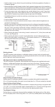
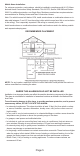
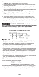
1. Turn off AC power to the circuit before wiring the AC quick connector
2. There are three pigtail wires (black, white and yellow) in the AC quick connector
3. Using wire nuts, make the connections as follows:
BLACK “Hot” side of AC line
WHITE “Neutral” side of AC line
YELLOW “Interconnect” wires from other alarms (OPTIONAL)
4. Repeat for each alarm in the interconnected system. The yellow wire is used for multiple
station installations with other USI Electric or Universal model alarms only. CAUTION: Con-
necting this yellow wire to any other circuits may result in damage and alarm malfunction.
Page 8