
Instruction Sheet


Page 6
Interconnected CO alarms or CO alarm circuit of combination smoke and CO alarms will only
respond if a CO alarm / event initiates the alarm. All other alarms remain silent.
Interconnected smoke alarms, heat alarms and relay modules will only respond if a smoke
alarm / event or heat alarm / event initiates the alarm. All CO alarms remain silent.
Note that smoke alarms without battery backup will not respond during an AC power failure.
NOTE: Relay Modules/USI-960 will not respond if a CO alarm / event initiates the alarm.
OPERATION, TESTING & MAINTENANCE
OPERATION: The smoke alarm is operating once the AC power is connected and turned on (the
battery must also be installed). When products of combustion are sensed, the alarm sounds a loud
alarm which continues until the air is cleared.
This alarm incorporates the NFPA recognized horn signal for evacuation. During alarm mode, the
horn produces three beeps followed by a two second pause and then continually repeats.
READY/ACTIVE CONDITION: The red LED blinks on once approx. every 40-45 seconds to indicate
the alarm is properly functioning.
LOCAL ORIGINATING ALARM CONDITION: The red LED blinks on approx. every 2 seconds and
the alarm emits a loud, pulsating alarm sound.
NON-ORIGINATING ALARM CONDITION: The red LED is off and the alarm emits a loud, pulsating alarm.
GREEN LED: The green LED is on whenever AC power is turned on.
NUISANCE ALARMS:
The smoke alarm is designed to minimize nuisance alarms. Smoking will
not normally set off the alarm unless smoke is blown directly into the smoke alarm. Combustion
particles from cooking may set off the alarm if the smoke alarm is located close to the kitchen
cooking surface. Large quantities of combustion particles are generated from spills or broiling.
If the smoke alarm does sound, check for fires first. If a fire is discovered, get out and call the fire
department. If no fire is present, check to see if one of the reasons listed above may have caused
the alarm. Use the Silence Feature if it is a nuisance alarm, or reset the alarm by pressing and
holding the test button for ten seconds. Refer to RESET on Page 7.
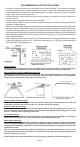
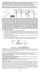
The yellow wire is used only for multiple station operations with USI ELECTRIC or UNIVERSAL
Model alarms only. Connecting this yellow wire to any other circuits may result in damage and
alarm malfunction. When alarms are interconnected, all alarms must be powered from a single
AC branch circuit. If local codes do not permit, be sure the neutral wire is common to both
phases. The maximum wire run distance between the first and last alarm/device in an
interconnected system is 1,000 feet. NOTE: Use standard household wire (18 gauge or larger,
rated at least 300V, as required by local codes) available at all electrical supply/hardware stores.
The wiring to be used shall be in accordance with the provisions of Articles 210 and 300.3(B)
of the National Electrical Code, ANSI/NFPA 70, Chapter 3 - Wiring Methods and Materials;
and National Fire Alarm Code, NFPA72, Chapter 11 - Single and Multiple Station Alarlm and
Household Fire Alarm Systems. In addition, the resistance of the interconnecting wiring shall
be a maximum of 10 Ohms.
2. Attach the mounting bracket to the electrical junction box.
3. To activate 9 volt battery and alarm, hold the QUICK DRAW
(R)
battery drawer closed, pull and remove
the PULL-TAB. Confirm that the entire PULL-TAB has been completely removed. Discard PULL-TAB.
4. Plug the AC QUICK CONNECTOR into the alarm base. Push and twist the alarm clockwise
onto the mounting bracket.
5. See "OPTIONAL TAMPER RESISTANT FEATURES" and "TO ACTIVATE THE LOCKING
FEATURES" instructions on Page 4.
6. Turn on AC power and check the LED's for proper operation. The green LED should be on to indicate
AC power. The red LED blinks on once approx. every 40 seconds to indicate proper operation.
120 VAC 60Hz