
Installation Guide

OPERATION, TESTING & MAINTENANCE
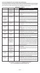
OPERATION: The smoke alarm is operating once the AC power is connected and turned on (the
batterymustalsobeinstalled).Whenproductsofcombustionaresensed,thealarmsoundsaloud
alarm which continues until the air is cleared.
This alarm incorporates the NFPA recognized horn signal for evacuation. During alarm mode, the
hornproducesthreebeepsfollowedbyatwosecondpauseandthencontinuallyrepeats.
READY/ACTIVE CONDITION:TheredLEDblinksononceapprox.every40-45secondstoindicate
the alarm is properly functioning.
LOCAL ORIGINATING ALARM CONDITION:TheredLEDblinksonapprox.every2secondsand
the alarm emits a loud, pulsating alarm sound.
NON-ORIGINATING ALARM CONDITION: The red LED is off and the alarm emits a loud, pulsating alarm.
GREEN LED: The green LED is on whenever AC power is turned on.
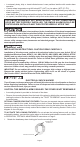
NUISANCE ALARMS:
The smoke alarm is designed to minimize nuisance alarms. Smoking will
notnormallysetoffthealarmunlesssmokeisblowndirectlyintothesmokealarm.Combustion
particles from cooking may set off the alarm if the smoke alarm is located close to the kitchen
cookingsurface.Largequantitiesofcombustionparticlesaregeneratedfromspillsorbroiling.
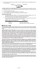
2. Attachthemountingbrackettotheelectricaljunctionbox.
3. Toactivate9voltbatteryandalarm,holdtheQUICKDRAW
(R)
batterydrawerclosed,pulland
remove the PULL-TAB. Conrm that the entire PULL-TAB has been completely removed.
Discard PULL-TAB.
4. PlugtheACQUICKCONNECTORintothealarmbase.Pushandtwistthealarmclockwise
ontothemountingbracket.
5. See "OPTIONAL TAMPER RESISTANT FEATURES" and "TO ACTIVATE THE LOCKING
FEATURES" instructions on Page 4.
6. TurnonACpowerandchecktheLED'sforproperoperation.ThegreenLEDshouldbeontoindicate
ACpower.TheredLEDblinksononceapprox.every40secondstoindicateproperoperation.
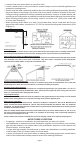
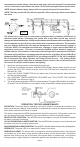
120 VAC 60Hz
100mAMax.
Interconnected smoke alarms, heat alarms and relays will only respond if a smoke alarm
event or heat alarm event initiates the alarm. All CO and natural gas alarms remain silent.
NOTE: Alarms without battery backup will not respond during an AC power failure.
NOTE: The relay, model USI-960, will not respond if a CO or natural gas alarm event initiates
the alarm.
Page 6
The yellow wire is used only for interconnect (multiple station operations) USI Electric or
Universal model alarms. Connecting this yellow wire to any other circuits may result in
damage and alarm malfunction. All interconnect alarms must be powered from a single circuit.
If local codes do not specify, be sure the neutral wire is common to all alarms. The maximum
wire run distance between the rst and last alarm/device in an interconnected system is
1,000 feet. NOTE: Use standard household wire, 18 gauge or larger, rated at least 300V, as
required by local codes. This wire is commonly available at most electrical supply and
hardware stores. The resistance of the interconnect wiring shall be a maximum of 10 Ohms.
The alarm wiring shall be in accordance with the provisions of Articles 210 and 300.3(B) of
the National Electrical Code, ANSI/NFPA 70. According to the NFPA 72 / Ed. 2013; paragraph
29.6.3 Household Fire Alarm Systems /AC Primary Power Source: “AC primary (main)
power shall be supplied either from a dedicated branch circuit or the un-switched portion
of a branch circuit also used for power and lighting.”