Please read these instructions before installing or commissioning. Potterton Solar - Solar Thermal Domestic Hot Water System should only be installed by a competent person. Please leave these instructions with the user for safe keeping. Commissioning, Maintenance & Servicing Guide Potterton Solar - Solar Thermal Domestic Hot Water System © Baxi Heating UK Ltd 2007.
Index 2 Index 3 Commissioning of system General information Flushing and filling the system 5 Commissioning of hydraulic station Checking/setting pressure Checking/adjusting flow rate Installation of thermal insulation 7 Commissioning of solar controller Overview of display Button function Operating menu Menu structure "Info" "Programming" "Manual operation" "Basic adjustment" Controller functions 21 Commissioning record 22 Servicing and maintenance record 24 Maintenance Check heat transfer fluid Main
1.0 1.1 Commissioning of system Commissioning - General The Potterton Solar system uses a sealed system indirect solar primary circuit which must be filled with the solar heat transfer fluid provided. This is pre-diluted to the appropriate strength (40% glycol/60%water) and should not be diluted further. Use only the fluid supplied. Additional canisters of solar fluid are available in 10 litre (5119550) and 20 litre (5119549) bottles. DO NOT mix the fluid with other types.
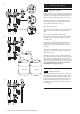
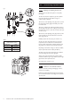
Fig. 1 3 5 4 1.0 1.2 Commissioning of system Flushing the pipework Before the system is commissioned the pipework must be flushed to remove any contaminants. It is recommended that this is done using the solar heat transfer fluid as it will be impossible to fully drain all parts of the system. 1 Connect the flushing pipes to the fill & drain valve on the safety group (Fig. 1 Item 1) and to the fill & drain valve on the flow meter (Fig. 1 Item 2). 2 Open the fill & drain valves.
2.0 2.1 Commissioning of hydraulic station Check pressure in the solar primary pipework After flushing and filling the solar primary system with heat transfer fluid the pressure must be checked. Pressure test the system (6 bar). Observe the maximum pressure ratings of all components concerned. Check the solar heating system for leaks. Close the fill and drain valve on the safety group. Fig. 4 2.
2.0 Fig. 5 1 2 Checking and adjusting the flow rate Adjust the flow rate when the system is cold (20°C) (see Fig. 5). The flow rate should be adjusted to give the optimum flow rate depending on the number and type of collector panels connected. 5 Turn the slot of the adjusting screw (Fig. 5 Item 1) below the return temperature gauge horizontally to close the non-return valve. Turn the l.h. isolating valve with integral thermometer in the flow (Fig.
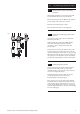
Fig. 7 Commissioning of solar controller 3.0 3.1 1 2 3 Overview of display and operating elements (see Fig. 7). Number 5 1 Description 3 Control button exit / break-off 2 4 4 5 Display with graphic symbols Control button scroll upwards / + Control button scroll downwards / – Control button choice / confirmation 3.1.
3.
3.1.2 Button function Operation and programming of the Potterton Solar differential temperature controller is by means of 4 operating buttons. By means of pressing these buttons you can: • recall display values • carry out controller adjustments The graphic symbols on the display step through the operating structure and show clearly the current menu points, display values or parameters.
3.0 Commissioning of solar controller 3.1.3 Operating menu To make the operation of the controller clear, operating and display functions are divided into 4 main menus. These are • Info • Programming • Manual operation • Basic adjustment Each active menu is shown in the upper line of the display by its corresponding icon.
3.0 Commissioning of solar controller 3.1.4 Overview: Construction of menu structure The overview shows the whole menu structure. According to basic adjustment and system type some menu points may not be displayed.
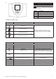
3.0 Commissioning of solar controller 3.1.5 Menu “Info” In this menu mode all measured values and operating states are shown. If the values are marked as “resettable”, they may be reset in the following way: Choose the value with buttons and Reset value by means of the button Message “OK?” confirm with 12 = no or = yes Indication Description Reset possible 75ºC Indication of current collector temperature no min.
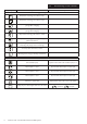
3.0 Commissioning of solar controller 3.1.6 Menu “Programming” All adjustable parameters can be checked in this menu and, if necessary, changed.The default factory set values will usually give efficient, problem free operation. The number of indicated values depends on the controller type and the adjusted additional functions. Only the required values are shown at each menu step: Indication Description Value range Defaults max 65ºC Storage 1/2: Maximum temperature 15..
3.0 Commissioning of solar controller 3.1.7 Menu “Manual operation” For commissioning, service and test purposes the solar primary system can be manually operated. For this purpose the switch outputs may be disconnected or connected. During manual operation there is no automatic regulation of the system.To avoid inadmissible operating states this mode of operation changes into “Indication” after ca. 8 hours and the automatic regulation is activated again.
3.0 Commissioning of solar controller 3.1.8 Menu “Basic adjustment” Adjustments and changes in this menu must be carried out only by a competent installer or service engineer. Incorrect adjustments may adversely affect the function of controller and solar primary system. To avoid accidental changes in menu “Basic adjustment”, it is not editable in normal functioning but has only a display function.
3.0 Commissioning of solar controller 3.1.9 Controller functions The Potterton Solar differential temperature controller contains many functions to regulate and monitor the solar primary system. Including - controller functions for heating the solar cylinder - functions for system protection and system monitoring - additional functions (other accessories may be required to achieve these functions). 3.1.
3.1.13 Rotational speed regulation The solar circulation pump on 230V-outputs A1 and A2 can be operated either in switch-mode (two-point controller) or in a rotational speed regulated way. If the rotational speed regulation is activated the pump power is adjusted by a controller so that switch-on temperature difference “Storage tank dTmax” is kept constant as much as possible. At lower deviation of “Storage tank dTmax” the pump is operated with the lowest power till the switch-off wave is reached.
3.1.16 Temperature difference control The temperature difference control manages an output according to adjustable temperature differential criteria. The function is independent from all the other functions. TDiff1 is the temperature of the heating source and TDiff2 of the heating target. Output A3 will be switched on regarding the conditions below, when a timeframe is active.
3.2.2 Flow monitoring If the energy productivity measurement option is deactivated, the temperature difference between collector and storage tank is checked. If it exceeds the amount of (60K + dTmax), it is then interpreted as an error because in the case of normal system dimensioning and a pump switched on such large differences cannot take place. If the energy productivity measurement option is activated, the flow amount when the pump is switched on is checked.
3.2.5 Frost protection This function can be switched on/off in the “Basic settings” menu, point 11 and the start temperature can be adjusted in point 13. Furthermore, a frost protection sensor can be selected (T1-T6, point 12). For systems driven without or with very low amounts of antifreeze, the pipes and the collector have to be protected from freezing. For this purpose, the selected frost protection sensor measures the temperature at an exposed place, e.g. blank pipes before the collector.
Commissioning record The following chart should be completed during Commissioning of the system.
Potterton Solar - Solar Thermal Domestic Hot Water System Engineers initials Visually check condition of any waterproofing (around pipe entries to roof and roof fixings) Visually check condition of collector panel brackets and fixings (every 2 years) Visually check condition of solar collector panels Ensure system is free of air Check solar cylinder in accordance with manufacturer's instructions Check sensor operation (use resistance/temperature table.
Potterton Solar - Solar Thermal Domestic Hot Water System 23 Engineers initials Visually check condition of any waterproofing (around pipe entries to roof and roof fixings) Visually check condition of collector panel brackets and fixings (every 2 years) Visually check condition of solar collector panels Ensure system is free of air Check solar cylinder in accordance with manufacturer's instructions Check sensor operation (use resistance/temperature table.
4.0 Maintenance 4.1 Check heat transfer fluid 4.2 Maintenance of the collector 4.3 Cylinder The heat transfer fluid must be checked every two years with regard to its antifreeze and pH value. - Check antifreeze using antifreeze tester.Target value is approximately -21 deg C (40% concentration). Do not allow to fall below 30% concentration. If necessary replace or replenish the solar heat transfer fluid. - Check pH value with a pH indicator rod (target value approx. pH 7.5).
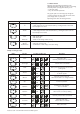
5.0 5.1 Fault finding Failures with error message Some system failure modes can be recognised by the solar differential temperature controller and will be indicated by an error message on the controller display. Refer to the table below for details of possible errors and suggested measures to rectify.
5.0 Resistance table PT1000.
5.
6.
S 6.0 6.1 Spare parts A number of Spare Parts are available should any part of the Potterton Solar system require replacement. Use only genuine parts obtained from Potterton, use of other non Potterton parts may cause system malfunctions and will invalidate the warranty. Fitting of any spare parts must be carried out by a competent installer or authorised service engineer or agent.
7.0 7.
7.0 Warranty What this warranty covers – Free of charge repair or replacement of components found to be faulty from manufacture. – Free of charge replacement of the complete assemblies provided always that the failure is related to a manufacturing fault that cannot be repaired or is beyond repair. The warranty runs for from the date your product is installed. What this warranty does not cover – Potterton Solar collectors that are installed damaged or damaged during installation.
All descriptions and illustrations provided in this leaflet have been carefully prepared but we reserve the right to make changes and improvements in our products which may affect the accuracy of the information contained in this leaflet. All goods are sold subject to our standard Conditions of Sale which are available on request. Potterton A Trading Division of Baxi Heating UK Ltd, a division of Baxi Group. Brooks House, Coventry Road,Warwick.