
Use and Care Guide

DO NOT TAMPER WITH WIRES WHEN POWER IS ON!
For alarms that are used as single non-interconnected, stand-alone alarms, do not connect
the yellow wire to anything. Insulate this wire (tape it) in place to make certain the yellow
wire cannot contact any metal parts.
INTERCONNECTION & COMPATIBILITY: Interconnected alarms can provide earlier warning
of re than stand-alone alarms, especially if a re starts in a remote area of the dwelling. When
alarms are interconnected, all alarms will sound when the initiating alarm sounds, providing more
time to escape safely.
This alarm may be interconnected with a total of not more than 24 interconnected devices, i.e., as
many as 11 other Mister Sparky Safety Sentry or compatible smoke alarms or combination smoke
and carbon monoxide (CO) or smoke and carbon monoxide/natural gas alarms; 6 other initiating
alarms which may be a combination of compatible CO alarms and heat alarms; and 6 other non-
initiating devices such as USI-960 relay modules.
This alarm can be interconnected with the following compatible models: ESD022W, ESD033W,
ESD004W, ESD004, ESD055W, MSD022W, MSD033W, MSD004W, MSD004, MSD055W,
MSD001E, 5304, MDSCN111, MICN109, MCN108, MI106, MDS107, MP117, USI-2430, USI-960,
MI106S, MIC1509S.
When any one of these interconnected models goes into alarm, it will trigger the corresponding
alarm within the interconnected system with respect to their sensing capabilities. Natural
gas detection is only present in models MDSCN111, MSDCN103, MICN109, and MCN108;
therefore, a natural gas alarm will NOT trigger the alarm of non-natural gas sensing models
within an interconnected system.
The following alarms can trigger QUICK FIND
®
Alarm Origination, but will not indicate Alarm
Origination on an interconnected system: USI-1103, USI-1203, USI-1204, USI-1208, USI-1209,
USI-1213, USI-5204, USI-3204, USI-7795, USI-2430, SS-2785.
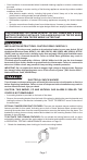
TO DEACTIVATE THE LOCKING FEATURES: To remove the alarm for cleaning or servicing or to
replace the battery, you must rst remove the appropriate locking pin, if it has been installed.
1. Turn off AC power to the circuit.
2. Use long nose pliers to pull the locking pin out of the hole.
3. It is now possible to remove the alarm or replace the battery.
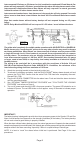
WIRING INSTRUCTIONS:
1. a. The appropriate power supply is 120 Volt single phase power supplied from a non-
switchable circuit NOT protected by a ground fault circuit interrupter.
b. Turn off AC power to the circuit before wiring the alarm.
c. There are three pigtail wires (black, white and yellow) coming from the AC QUICK
CONNECTOR. The proper wire connection is as follows:
WIRES FROM QUICK CONNECTOR CONNECT TO
BLACK “HOT” side of AC line
WHITE “NEUTRAL” side of AC line
YELLOW Interconnect wires of other alarms
Page 8
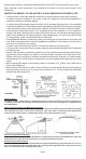
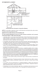
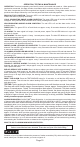
2. Insert the pin into the hole for the feature you are activating. Refer to the diagram below for
correct placement.
INSERT ALARM
LOCKING PIN
HERE
INSERT BATTERY
LOCKING PIN HERE