
Specifications


Ringing in Series II peripherals 3-11
DMS-100 Ringing System
The following table contains brief functional descriptions of the ringing
hardware associated with the SCM-100S/RCS ringing. A detailed description
of the SCM-100S hardware can be found in the SMS Maintenance Manual
RCS hardware
The RCS consists of the SLC-96, manufactured by AT Technologies, Inc. For
a detailed description of the SLC-96, refer to documentation provided by AT
Technologies, Inc.
Ringing generator capacity
The RCS ringing generator can ring a maximum of 5 lines per phase, 15 per
ringing cycle for single-party ringing.
Ringing generator takeover
The RCS is equipped with two ringing generators. One ringing generator
serves as the active unit and the other the standby. If the active ringing
generator fails, the standby ringing generator is brought online and a ringing
generator alarm is raised.
LCM ringing functional description
A clear understanding of the LCM ringing operation requires a basic
knowledge of the LCM hardware architecture. Each shelf of an LCM contains
five physical line drawers; a total of 10 line drawers make up each LCM. Each
physical line drawer can be further subdivided into two logical drawers,
sometimes called line subgroups (LSG). Each logical drawer contains up to 32
line cards connecting to a bus interface card (BIC) located in the physical line
drawer. The status of logical drawers is shown at the MAP when the LCM is
posted.
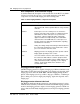
Table 3-8 SCM-100R ringing hardware component description
Component Description
NT6X45 Control complex. The SCM-100S control complex
coordinates call processing between the RCS and the
DMS-100. The control complex directs the RCS to establish
connections, collect digits, apply ringing, and disconnect
calls under the direction of the DMS-100 CC.
NT6X80 Ring/pad. The ring/pad circuit card provides PCM samples of
ringing signals. The control complex, upon determining the
type of ringing required for a given line, accesses the sample
PCM signal from the ring/pad card memory.
NT6X85 DS-1 Interface. The DS-1 interface card converts parallel
data from the DMS-100 CC to a serial format for
transmission over the DS-1 links to the RCS.