
Specifications


Ringing in Series II peripherals 3-41
DMS-100 Ringing System
At the frame
10
Put on a wrist strap.
11 Power down, remove, and make the DIP switch changes to RG-1.
Refer to the
Hardware Description Manual
, 297-8991-805 for information on
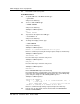
DIP switch settings for the ringing generator. The following figure shows the
DIP switch layout for the NT6X30AA ringing generator. Refer to the DIP
switch layout and settings for the ringing generator used in your office.
WARNING
Static electricity damage
Before removing any cards, put on a wrist strap and connect it to the
wrist strap grounding point on the left side of the frame supervisory
panel of the LCM. This protects the equipment against damage caused
by static electricity.
WARNING
Equipment damage
Take the following precautions when removing or inserting a card:
1. Do not apply direct pressure to the components.
2. Do not force the cards into the slots.
Locking lever tabs
Top view
SW1SW2SW3SW4
Faceplate
NNoottee: “On” and “Off” settings for DIP
switches can differ among ringing
generators.
12345678 12345678 12345678 12345678