
Operating instructions


Part 1 – Introduction
9
Overview
Product color and design may vary depending on the model.
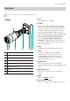
Body
12 3
8
4 5 76
1
Lens
2
IR LED
3
Body
4
Stand
5
Bottom Cover
6
Mounting Bracket
7
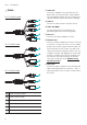
Cable
8
Sun Shield Screw Hole
1 Lens
Optical zoom lens is installed.
2 IR LED
A sensor in the bottom middle monitors lighting
levels and activates the IR LED during low-lighting
conditions. The PIR (Passive Infrared) sensor in
the upper middle of IR LEDs detects motions by
detecting infrared radiation changes at night or
under low lighting conditions (
DC-T1234WR model
only
). The motion detection by the PIR sensor
activates alarm out according to the settings of
Alarm Out (Remote Setup > Event Action >
Alarm Out), and the white LEDs which are at the
left and right middle of IR LEDs are lit while the
alarm out is activated.
3 Body
The cables are connected through the stand.
4 Stand
Allows you to adjust the camera direction
and lens’ rotation angle. Twist the setscrews
counterclockwise and move the camera to
the desired direction. Once it is set, twist the
setscrews clockwise to lock it.
5 Bottom Cover
Allows you to mount the camera to the wall or
ceiling using the mounting bracket provided with the
camera.
5 Mounting Bracket
Allows you to mount the camera to the wall or
ceiling.
5 Cable
Refer to the Cable on page 10
6 Sun Shield Screw Hole
Allows you to screw the sun shield to the camera.