
Setup guide

USP 507 • Setup Guide (Continued)
2
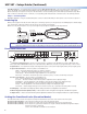
Aux SW Follow port — For auxiliary device switching; using a NULL RS-232 cable only, connect an Extron audio switcher/processor,
such as the SW 8A, to the lower 9-pin D-sub RS-232 connector
n. When the USP 507 switches input via either a control device
RS-232 command, or front panel control, the USP 507 and the connected auxiliary device will switch inputs simultaneously. When
video is muted or unmuted, frozen or unfrozen, a corresponding audio mute/unmute command is sent to the auxiliary switcher.
Step 5 — Connect power
AC power connector — Plug in a standard IEC power cord from a 100 to 240 VAC, 50 - 60 Hz power source into this receptacle
a
.
Powering Up
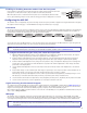
When powering up the USP 507, the unit undergoes a self testing sequence (see image below). The LCD displays the default display
cycle, showing the output rate and the refresh rates for the currently selected input.
When not in any menu mode the screen cycles through the input/output configuration currently installed.
3
sec.
10
sec.
Apply
Power
Extron
USP 507 v1.xx
1
sec.
2 sec.
2
sec.
Default Display Cycle
Input #2
60.0kHz 75.0Hz
1024x768 60.0Hz
Output Rate
Menu and Next
buttons remain lit.
All buttons flash in sequence
(green, red, amber).
MENU
NEXT
1
sec.
2
1
1
sec.
2
1
Last active input
button remains lit.
= unlit
= lit
= flashing
Key
3
sec.
NOTE: When in use and not in any menu mode, the LCD screen defaults to cycling through the current input/output
status. The displayed content may vary depending on the input video signal type (see typical default display above).
Front Panel Overview
USP 507
UNIVERSL SIGNAL PROCESSOR
ADJUST
DETAIL
ZOOM
/PAN
BRIGHT
/CONT
COLOR
/TINT
SIZE
POSITION
MUTE
AUTO
IMAGE
FREEZE
6 754321
MENU
NEXT
INPUTS
PIP
PRESET
1
2
5
3
4
6
7
a
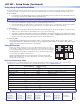
Front panel configuration port — Connect a control system or computer to this (RS-232) port, using a TRS RS-232 cable,
Extron part number 70-335-01. RS-232 protocol (default values): 9600 baud, 1 stop bit, no parity, 8 data bits, no flow control
b
Input buttons — Selects/switches inputs, indicating which input is active (current input lights amber, PIP input lights green).
c
Special function buttons — These four, dual colored buttons are:
• Mute — Allows the displayed image to be muted or umuted.
• Freeze — Allows the current displayed image to be frozen or unfrozen.
• Auto Image
™
— Allows automatic image adjustment on selected input.
• PIP Preset — Allows the current PIP layout to be saved as a preset, or recalls a saved PIP preset layout.
d
Picture contol buttons — These six, dual colored buttons are:
• Size — Allows adjustment to the displayed image size.
• Position — Allows horizontal and/or vertical position adjustment of the displayed image.
• Bright/Cont — Allows adjustment of the brightness and contrast settings for the displayed image.
• Color/Tint — Allows adjustment of the color and tint settings for the displayed image.
• Detail — Allows adjustment of the detail (sharpness) setting for the displayed image.
• Zoom/Pan — Allows displayed image to be zoomed in or back out, or panned horizontally and/or vertically.
e
LCD display — This 16x2 screen displays device settings and menu configuration information.
f
Menu navigation buttons (Menu, Next) — These buttons allow navigation through the USP 507 menu system.
g
Adjust knobs — These are used with the picture adjustment and the menu navigation buttons to adjust settings.
Setting the Front Panel Locks (Executive Modes)
The USP 507 has three modes of front panel security lock that limit the operation of the unit from the front panel.
Executive mode 0 (disabled) — The front panel is fully unlocked. This is the default setting.
Executive mode 1 (enabled) — The front panel is locked except for input switching, video freeze, and auto image.
Executive mode 2 (enabled) — The front panel is completely locked and can only be enabled and disabled using Extron Simple
Instruction Set (SIS
™
) commands.
See the online USP 507 User Guide for SIS commands.