
Setup guide

1
Product Category
USP 507 • Setup Guide
The Extron USP 507 (Universal Signal Processor) is a scaling product that allows most common signal formats to be processed and
output in any desired format.
This set up guide allows an experienced user to easily and quickly set up and configure a USP 507 using step by step instructions.
It covers performing basic operations using the front panel controls and selected Simple Instruction Set (SIS™) commands.
NOTE: For full installation, configuration, menus, and operation details, see the USP 507 User Guide at www.extron.com
Rack Mount
Bracket
Installation
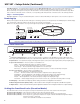
Rear Panel Features
Power and video input connections
Output, user interface, and control connections
Mounting and Cabling
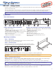
Step 1 — Mounting
Turn off or disconnect all equipment power sources and rack mount the USP 507
using the supplied brackets (see image at right).
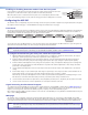
Step 2 — Connect inputs
Connect inputs from video sources to the applicable connectors marked “Inputs”.
See
b through g above for connector types and the image below for signal format.
RGBHV
H/HV
R/
R-Y
V
G/Y
VID
B/C
B-Y
R/
R-Y
V
G/Y
VID
RGBS/ RGBcvS video
H/HV
B/C
B-Y
R/
R-Y
B/C
B-Y
RGsB/Component Video
(R-Y, Y, B-Y)
H/HV
V
C
S-video
VID
/Y
Composite
video
VID
/Y
C
G/Y
VID
Step 3 — Connect outputs
Connect video output devices to the applicable connectors marked “Outputs” (see h through k above).
CAUTION Do not connect an MTP cable to the LAN port, or connect a LAN cable to the MTP port.
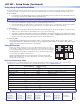
Step 4 — Connect control devices
LAN Ethernet port
l
— Connect an Ethernet LAN or WAN via this RJ-45 connector for remote control of the USP 507 using an
Internet browser on a connected PC, or the Extron Signal Processing Product Control Program (SPPCP).
One Ethernet connection LED lights green when connected to the LAN and one flickers amber as the devices communicate.
NOTE: Do not use standard telephone cables for LAN connection, as they do not support Ethernet or Fast Ethernet.
Do not stretch or bend cables as transmission errors could occur.
RS-232 ports — For serial RS-232 or RS-422 control, connect a host computer or control system to the upper 9-pin D connector
m
.
RS-232 protocol (default values): 9600 baud, 1 stop bit, no parity, 8 data bits, no flow control.
a AC power connector
h
RGB/HD, component, BNC connectors
o
Reset button and LED
b
RGB/HD, component, VGA connectors (inputs 1 and 2)
i
RGB/HD, component VGA connectors
c
Universal BNC connectors (input 3)
j
(Optional) output card*
d
Component/S-video/composite BNC connectors (input 4)
k
MTP twisted pair connector
e
S-video/composite video BNC connectors (input 5)
l
RJ-45 Ethernet connector
f
DVI connector (input 6)
m
Control device 9-pin D-sub RS-232 connector
g
(Optional) HD-SDI/SDI connector (input 7)
n
Auxilliary switcher 9-pin D-sub RS-232 connector
*DVI card shown
100-240 VAC 2A MAX
AUX SW FOLL0W
RS-232
B-Y
/C
R-Y
HDSDI/
SDI
C
RGB/R-Y, B-Y, Y
DVI
OUT
DVI-D
VID
/Y
5
4
3
2
VID
1
R/
R-Y
G/
Y
B/
B-Y
H V S
R/
R-Y
G/Y
B/C
B-Y
H/HV
V
O
U
T
P
U
T
I
N
P
U
T
50-60Hz
RGB/R-Y, Y, B-Y
VID
/Y
RGB/R-Y, Y, B-Y
7
6
LAN
RESET
7
10
12
15
1
2
5
3
4
6
9
11
8
14
13
MTP