
Technical data


Technical Manual Cold Storage Controllers TKP / TKC x130 - x140Page 24
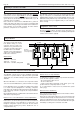
Basic Configuration of TKP 3130/1
Because the TKP 3130/1 has no own operating elements and no
display, the basic configuration must be done in a special way.
Sequence
l Note: The network adress of the cntroller unit ("
adress in netwk
",
Mode Page) is factory set to '78'.
l Prepare VPR-System
l Connect a single TKP 3130/1 to the RS-485-Line interface.
l Open subpage "Service Data" at the VPR-Display.
l Set desired network adress for the TKP at parameter "
Change
CST adress
".
l The new adress will be transmitted to the TKP.
l As usual, the TKP can be inserted and programmed on the
CST-pages of the VPR-System.
l Connect next controller to the interface and repeat procedure.
During configuration, also multiple controller units can
be connected to the line-interface.
It makes sense that only one of this owns the adress '78',
because the configuration function transmits the new
adress only to units with the factory set adress '78'.
Connecting multiple new TKP 3130/1 at the same time
doesn't work.
Please read before Start-up
• Limit of Application: This product is not designed nor
manufactured for use in equipment or systems that are
intended to be used under such circumstances that may
affect human life.
For applications requiring extremely high reliability, please
contact the manufacturer first
• Electrical installation and putting into service must be
done from authorized personnel.
• Please note the local safety instructions !
• Before installation: Check the limits of the controller and
your application. Before starting up we recommend you to
read the following instructions for use, since only by doing
so you can avoid damage or malfunction and you will
benefit all the advantages offered by this product.
• During installation and wiring never work when the
electricity is not cut-off !
• Mounting the controller close to power relays is
unfavourable in case of the electro-magnetic interference.
• Before applying voltage to the controller:
Make sure that all wiring has been made in accordance
with the wiring diagram in this manual.
Check, if the supply voltage corresponds to the value
printed on the type label.
• Connect the ‘PE’ terminal carefully to ground because
otherwise the operation of the internal noise filter will be
disabled.
• Respect the environmental limits for temperature and
humidity. Outside these limits malfunctions may occur.
• Never operate unit without housing.
• In case of malfunction or doubts please contact our
technical support.
• Observe the maximum admitted current rate for the
relays (see technical data). Compare with the peak start-
up current of the controlled devices (valve, fan,
compressor, heater..)
• Sensor cables may be up to some hundred meters in
length. Use shielded sensor cable only. Don’t install them
in parallel with high-current cables to prevent inductive
interference. A cross section of min. 0,5mm² is sufficient.
• Shielding has to be connected to PE at the end near the
controller
• All used temperature sensors must be identical. Never
use PTC (TF 201) and PT1000 (TF 501) mixed. This will
not work.
• TF-type sensors are moisture-proof but they are not
designed for being immersed in water for a long period of
time (not pressure-proof). In such a case, always use dip-
fittings.
• Be care that the wiring of interface lines meets the
requirements
CONNECTION & SAFETY INFORMATIONS
With this controller type, only sensors of the TF 501
series (Pt1000) can be used.