
Technical data


Technical Manual Cold Storage Controllers TKP / TKC x130 - x140 Page 23
Installation / Getting Started
Upon applying voltage to the controller, the display shows after a few
seconds type, date and time or the parameter which is selected as
permanent display, the display backlight is off. Pressing any key
turns the backlight on. If the controller is applied to voltage the first
time, you are now invited to change or confirm the language.
Putting into operation
• check and/or set the actual time and date of the controller
• determine the function of all inputs and outputs on the assignment
page. (only possible in the 'configuration level', which is the factory
setting. See also page 11). Unless you haven’t done this, you will
not see all necessary parameters on the other pages!
• select type of used temperature sensors („
sensor
“, mode page).
• correct the displayed temperature values if necessary
(„
corr sensor..
“, mode page).
• set date and time
• select the desired „defrost mode“ (defrost page) and if the fan
should turn during defrost or not.
• select cooling mode on mode page
(note: will influence the electrical connection of the relay.)
These are the most important steps for the basic configuration of the
controller. Upon that, adapt the other parameters like temperature
setpoint, hysteresis, delay times.... Refer to the previous chapters in
this manual.
Start-up in a data network
• set the adress of the controller (mode page)
• verify the baudrate (mode page)
• Load the parameters form the PC to the controller (upload).
Start-up with a PC/Laptop
The start-up of the controller can be much easier by using a PC and
the software "COOLVision-MES". In this case the controller will be
connected via the RS-232 interface.
• set the adress of the controller (mode page)
• remote control of the unit from the PC
As a result of its text display the controller offers you the chance of
getting an overview about the plant in a very short time.
E.g. possibility to see the values of:
· temperatures (all sensors) · remaining delay times
· analog value · state of the digital inputs
· state of the relais · actual and historic failures
If failures are present, they are listed on "act.failure
page"
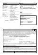
Sensor Positions
The controller needs correct
temperature input in-
formation to work correctly,
but sensor positions are not
critical.
The control sensor for
regulation or alarmsensor
has to be fixed behind the
evaporator (air inlet) or at a
representative place in the
chamber, but not in the air
outlet
The second sensor (defrost sensor or evaporator sensor) should
be assembled in the tube which is factory provided for this purpose.
If the evaporator has not such a tube, assemble it between the fins
in the upper part and assure a good thermal exchange. It should be
placed at the position
where the icing stays
the longest time when
defrosting. This
depends of type and
manufacturer of the
evaporator, so use your
experience.
Make sure that the
sensor doesn’t touch
the heater or any piping
with hot gas defrost, it
must have some
distance to these heat
sources.
We indicate that remaining ice in an evaporator even after a defrost
period is due to sensors which have not enough thermal contact or
which are installed at a wrong place. If you encount icing you should
place the defrost sensor to this area.
Sensors for demand defrost (TKP x140)
To detect icing the TKP x140 does not need more sensors than the
normal ones. The controlsensor and the defrost sensor are sufficient.
Sensors for demand defrost (TKP x130)
If the TKP x130 is set to demand defrost by differential method two
additional sensors are necessary to record the temperature difference
across the evaporator. Mount the „cold“ sensor directly to the 2nd or
3rd elbow of the evaporator tube and the „warm“ sensor in the
evaporator outlet air (but not above the fan - the motor will dissipate
heat when cut off). Control sensor and defrost sensor are placed in
the same way as explained above.
evap sensor
control
sensor
airflow
contact -
pipe
fins
connector case
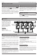
PC with Software
COOLVision-MES
SUB-D, fem., 9 poles
7
8
6
5
2
3
4
Pin
1
white / brown
y
ellow
g
reen
39
OUT
46
GND
RS
232
4140
IN
DO
NDO
RS
485
42 43
PC-connection of a single controller for configuration-
or service purposes.
cable Order-No.: PC-SMZ/KLEMME