
Technical data


Technical Manual Cold Storage Controllers TKP / TKC x130 - x140 Page 15
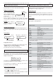
PID
integral time
proportional band
min.
output
setpoint-
deviation
max.
5V resp. 12mA
P-part
t
I-part
t
t
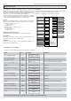
PID delay
proportional band
min.
output
5V resp. 12mA
PID
integral time
P-part
I-part
setpoint-
deviation
max.
t
PI-control,
D and T1-parts
de-activated
PID-control,
T1-part
de-activated
PID-control,
with T1-
low-pass filter
t
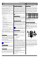
PID attack time
PID
integral time
proportional band
min.
output
5V resp. 12mA
P-part
I-part
setpoint-
deviation
max.
t
Analog Output
The TKP / TKC contains an analog output which can be used for
regulation or to provide a remote display with an actual value image.
The signal is available as a DC-Voltage or a DC-Current-Signal.
Parameter „
analog value
“ (actual page) shows the current output
signal as a %-part of the selected range, "
analog function
" (assignment
page) determines the behaviour of the output:
Test functions
0V = voltage = 0V, current = 0 mA fixed
4mA = voltage = 2V, current = 4 mA fixed
10V/20mA = voltage = 10V, current = 20mA fixed
Transmission of actual values to remote displays or similar
act.img 0-10V =The outputs provide an image of the value of
refrig.sensor 1.
voltage: -50°C = 0V, +100°C = 10V
current: -50°C = 0mA, +100°C = 20mA
act.img 4-20mA = The outputs provide an image of the value of
refrig.sensor 1.
voltage: -50°C = 2V, +100°C = 10V
current: -50°C = 4mA, +100°C = 20mA
Control with the analog output signal (PI-control)
PID-T1 0-10V = This PID-controller with 0-10V DC-signal is
assigned to cooling circuit 1. The output signal
represents an addition of the components P, I, D
and T1.
PID-T1 4-20mA = This PID-controller with 4/20mA-signal is
assigned to cooling circuit 1. The output signal
represents an addition of the components P, I, D
and T1.
PID-T1 10-0V = PID-controller like above, but with inverted voltage
output (rising temperature = falling voltage).
PID-T1 20-4mA = PID-controller like above, but with inverted
4/20 mA-output
(rising temperature = falling current)
To adapt the controller to the process use the following parameters:
" PID propor band" ......
situated symmetrically to '
setpoint Ch 1
'
" PID integr time"
......... integral time (I-part)
" PID attack time"
........ derivative time (D-part)
" PID delay"
.............. actuator response time (T1-part)
How to affect the analog output manually
For certain operations it might be usefull to affect the output signal
manually. Therefore the function „
analog value
“ (assignment page)
can be assigned to one of the digital inputs.
Applying mains phase to the digital input the analog output will be
forced to the value (in %) that is programmed by „
opto->analogout
“
(setpoint page). So e.g. a connected valve drive will be set to a
specific position.
Control Characteristic