
Technical data


Technical Manual Cold Storage Controllers TKP / TKC x130 - x140 Page 11
Display of actual values and states
All actual values are shown on the '
actual values
' page.
Display of the temperatures
'
sensor1
' to '
sensor 6
' display
their actual value in the range
of -50 ... +100°C. On the same
time, the display shows the
functions which are assigned
to the sensor.
Sensor corrections can be
made by editing each individual sensor reading. The resulting
correction factors are listed on the mode page (
corr sensor 1-6
).
Setpoints:
The active day or night set-
points are indicated on the
display by „->“ and „<-“.
Information about delay times
On the actual values page you will find all remaining delay times, so
it is easy to verify the points in time when specific functions must
start.
Status Displays
Temperature Sensors
There are two types of temperature sensors which can be used:
- TF 201, PTC sensor (2000 ohms@25°C), !! not 3130/1 !!
- TF 501, PT1000 sensor (1000 ohms@0°C)
The type must be preset by '
sensor
' (mode page).
'Permanent Parameter' - Function (Basic Display)
After switching on the controller, the display will indicate the 'perma-
nent parameter' after some seconds (or in case of a failure it will
display the actual failure):
This will also be showed if you have selected some parameters and
you don’t touch a button for more than 3 minutes.
If you think that it is suggestive to show any sensor value as
permanent parameter, do the following:
Change permanent parameter
- Select parameter you want to have as 'permanent parameter'
- Press and simultaneaously.
The display becomes dark for a moment, after that the selected
parameter will be shown as basic display.
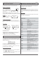
sensor 1 R1A1--
-24.5°C
1. function
2. function
3. function
setpoint CH 1
-> -22.5°C <-
active setpoint is marked
TKP/TKC
18.01.00 09:24
ñ
ò
Failure Messages / Failure Memory / Failure Codes
All failures will be memorized with date and time of their appearance.
To display this messages, 2 pages exist:
Actual failures page
This page contains all current failures in a short form. To make more
than one current failure visible, use the 'up/down'-keys. If a sensor
is short or broken, this message also appear on the actual value
display.
Historic failures
On this page you will always find the last 15 failures memorized with
date and time of their appearance.
Failure Codes
---- no failure
Init first initialisation of the controller
or data lost
Hard hardware failure
MOFF mains supply cut off
MON mains supply switched on
SiCh security chain open
SBr X sensor X broken
SSH X sensor X short
If a sensor is short or broken, a time delay of 5 seconds takes effect before
an alarm will be activated.
HT X one of the alarm sensors of circuit X
high temperature
LT X one of the alarm sensors of circuit X
low temperature
MRC X cooling of circuit X has exceeded maximum
runtime. This message is only active up to
'
runtime mess at
' (mode page).
OPC X alarm on digital (OC) input X, assigned as
alarm input
DOR X door contact of circuit X open too long. This
message is only active up to '
runtime
mess at
' (mode page).
DEF X number of defrost cycles without
termination by temperature exceeded in
circuit X, maybe too many ice or heater
malfunction.
ASSI error on assignment page,
e.g. function programmed too often
COon controller unit switched ON by interface
or by digital input
COof controller unit switched OFF by interface
or by digital input
OFF X circuit X switched off by interface or by
digital input
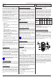
relay status
0 1 0 1 1 1
1 = relay activated
0 = relay de-activated
Relay 1.......................Relay 6
OC1 OC2 OC3 OC4
0V 230V
0V = no voltage
Optocoupler 1.......Optocoupler 4