
Specifications


42” HD Gas Plasma Display Rosen Aviation Displays, LLC
8
DVI (Digital Visual Interface)
If your new display is being used with a computer with DVI output, connect a DVI cable to
this connector location and the other end to your computer. Your cable should not be
longer than necessary.
Analog RGB Input (Computer)
If your new display is being used with a computer that has only a VGA output, connect a
VGA cable with a DVI-Analog connector to this DVI/RGB connector location (see Figure 2
on page 7), and connect the other end to your computer’s VGA feature connector. Your
cable should not be longer than necessary.
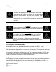
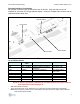
Analog RGB Used as Component Video (YPrPb)
With the use of proper cabling as shown in Figure 3, the unit can also be set up to accept
HDTV component video (YPrPb) on the analog RGB input. Adjustments on the OSD are
also needed. Under Source Setup, HDTV Input should be turned ON and Color Space
should be changed to YUV HD. The remote control and OSD arrangements for this
configuration are described in more detail in Appendices B and C (pages 22 and 30).
Figure 3
HDTV Component Video (YPbPr.2)
If your new display is to be used with a video source that uses HDTV Component Video
interconnection, connect your BNC cables to the BNC connectors labeled Y, Pr, and Pb.
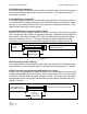
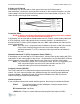
YPrPb.2 Used as Computer Analog RGB with Sync on Green
With the use of proper cabling as shown in Figure 4, the unit can also be set up to accept
computer analog RGB with sync on Green. Under Source Setup, HDTV Input should be
turned OFF and Color Space should be changed to RGB. The remote control and OSD
arrangements for this configuration are described in more detail in Appendices B and C
(pages 22 and 30).
Figure 4
3 Coax
to HDB15
Adapter Cable
HDB15 to DVI-A Adapter Connector
Plugged into Monitor
YPrPb
Source
3 Coax
from HDB15
Adapter Cable
BNC Connectors plugged into Monitor
Analog RGB Source
With HDB15 Connector
3 Coax
from HDB15
Adapter Cable
Anolog RGB Source
with HDB15 Connector
BNC Connectors Plugged into Monitor